Programmable DC Power Supply 62000P Series Operating & Programming Manual
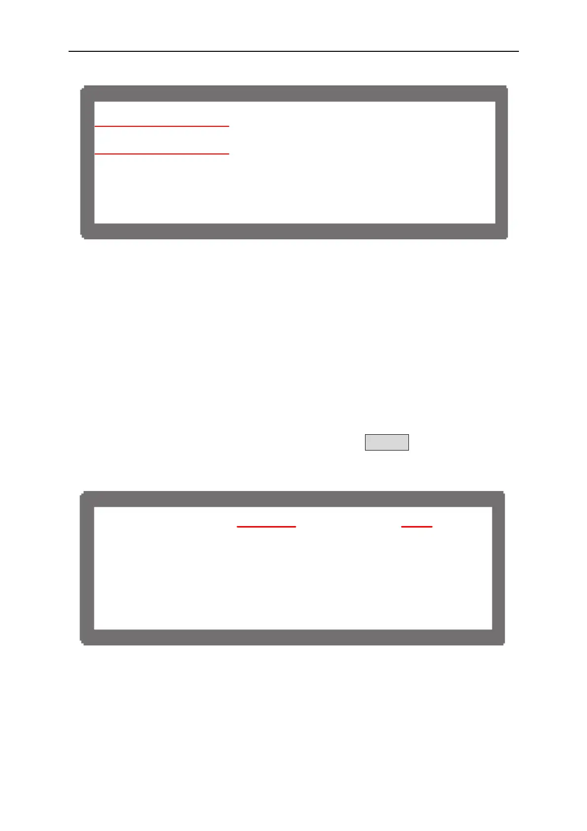
[PRO T E C T I O N]
Σ
O V P O = 4 4 0 . 0 V
O C P O = 6 3 . 0 A
Σ
O P P O = 6 0 0 0 . 0 W
F O L D B A C K F = D I S A B L E
Figure 3-41
3.3.3.5 Setting Parallel Parameters
When the software communication and hardware settings for parallel are completed, the
settings of following windows are introduced in the sections underneath - (1) MAIN PAGE,
(2) SYSTEM SETUP and (3) OUTPUT SETUP.
3.3.3.5.1 Setting MAIN PAGE
MAIN PAGE is mainly used to set voltage (V_SET) and current (I_SET). The difference
between single unit and parallel operation is that the current set will increase following the
number connected in series. The current set is indicated by ΣI_SET for easy identification.
When set to MASTER, MST will appear at the window’s upper right corner as Figure 3-42
shows.
V _ S E
= 8 0 . 0 0 V
I_SET=15.00A
M
S T
O F F
0 0 . 0 0
00 . 00A
0 .
W
Figure 3-42
3-28

 Loading...

