Manual Operation
3.3.3.5.2 Setting SYSTEM SETUP for Parallel
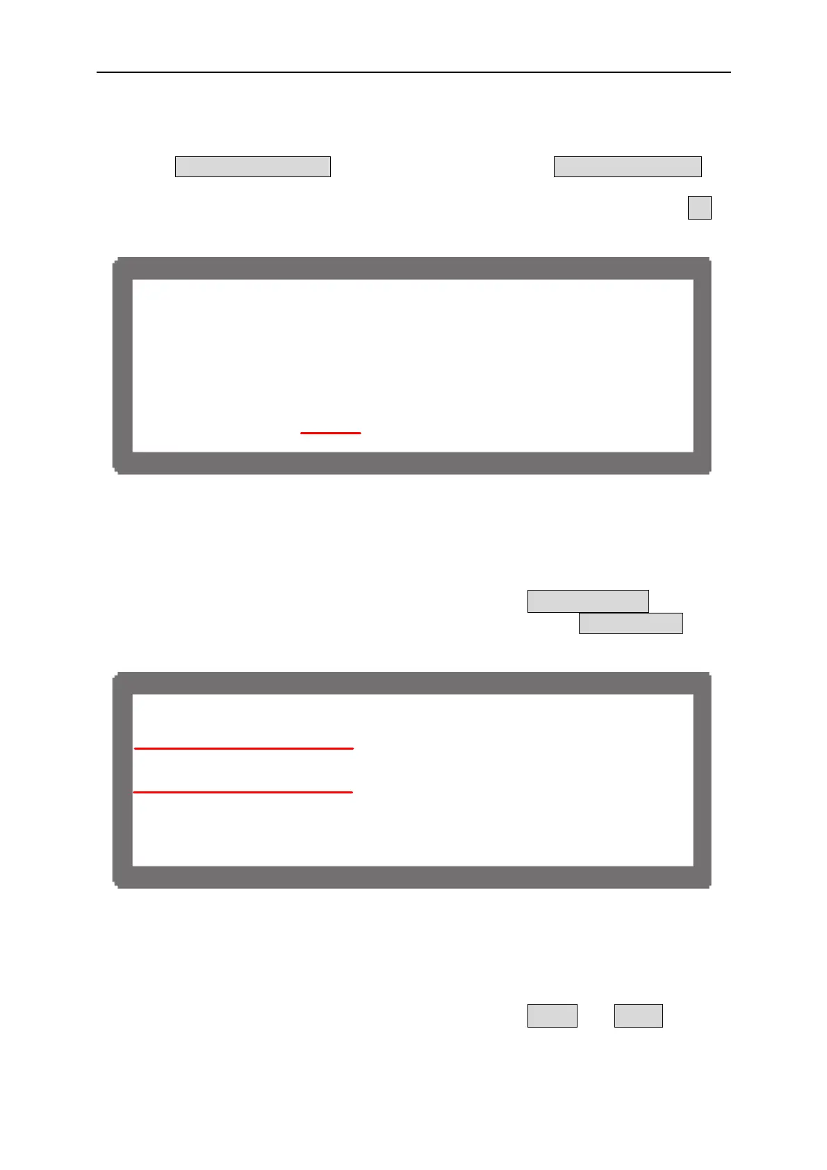
The option POWER ON STATUS in SYSTEM SETUP must set to USER DEFINIITION
when connected in parallel along with the output current. The current set increases
following the number connected in parallel and for easy identification it is indicated by ΣI
as Figure 3-43 shows.
[S
S
E
SE
U P ]
G P I B A D D
= 1
R S - 2 3 2 B
U D R
T E= 9600
A P G = NONE
B A C K L I G H
= HIGH
B U Z Z E R = ON
P O
E
O N S T A
U S = USER DE F I N I T I O N
V = 8 0 . 0 0 V
Σ
I = 6 0 . 0 0 A O U T P U
= O
Figure 3-43
3.3.3.5.3 Setting OUTPUT SETUP for Parallel
The I LIMIT MAX in OUTPUT SETUP of MASTER for parallel connection will increase
following the number connected in parallel. It is indicated by ΣI LIMIT MAX: for easy
identification as Figure 3-44 shows. Furthermore, the setting range of I SLEW RATE will
increase following the number connected in parallel too.
[O
TP
S E
U P ]
V L I M I T : M
X
80 .0 0 V M I N
000 . 0 0 V
Σ
I L I M I T : M
X
15 .0 0 A M I N
000 . 0 0 A
V S L E W
A T E
1.00(V/mS)
Σ
I S L E W
A T E
1.00(A/mS)
T T L V A L U E
0(DE
)
< B I N A R
00000000>
Figure 3-44
3.3.3.5.4 Setting PROTECTION for Parallel
The OCP and OPP in PROTECTION of MASTER for parallel connection will increase
following the number connected in parallel. It is indicated by ΣOCP and ΣOPP for easy
identification as Figure 3-45 shows.
3-29

 Loading...

