Installation
2.5.3 Reverse Connection of Remote Sensing Wire Polarity
The polarity of remote sensing wire must be connected correctly, that is the “+” terminal is
connected to the “+” of output terminal or to the connecting wire of the terminal, while the
“-” terminal is connected to the “-” of output terminal or to the connecting wire of the
terminal. If the polarity is connected reversely, the output will drop to 0V and prompt an
error message “RMT FAULT” as Figure 2-7 shows.
V _ S E T = 8 0 . 0 0 V I _ S E T = 1 5 . 0 0 A O F F
0 0 . 0 0 V 00 . 00A
0 . 0 W
S E N S E F A U L T
Figure 2-7
NOTICE
The DC Power Supply does not burn down due to reverse connection of polarity. Do the
following step to reset it:
1. First power it off.
2. Connect the remote sensing wire properly.
3. Restart the DC Power Supply.
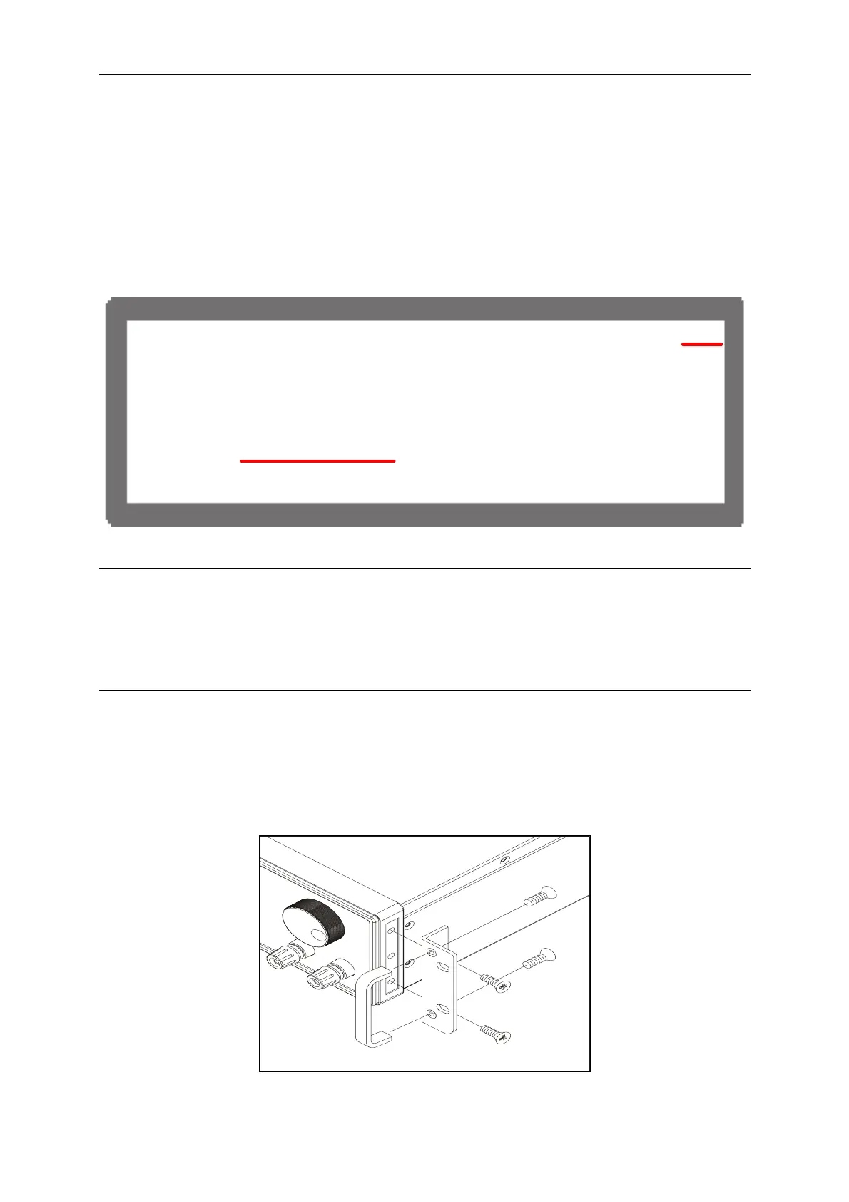
2.5.4 Rack Mounting Kit & Handle Installation
Remove the sliver inlay from the plastic side frame and use M4X15 flat head screws to secure
the rack mounting kit to the plastic side frame. If a handle is required for installation, use
M4X9 flat head screws to secure it to the rack mounting kit as shown below.
Figure 2-8
2-7

 Loading...

