Theory of Operation
6. Theory of Operation
6.1 Overview
The 62012P Series DC Power Supply has A, B, C, D, G, I, K, M, N and S total 10 circuit
boards in it.
A board contains input stage and auxiliary power.
B board is the output stage.
C board is the digital control board.
D board is the connecting board from digital board to LCD panel.
G board is the GPIB control board (optional).
I board connects the RS232, RS485, TTL and APG signals to rear panel.
K board controls the keys connected to front panel.
M board connects S board and B board. It is the control board connecting Current
Sharing and Remote Sense wire in parallel for reverse protection.
N board connects to the output copper bus to filter out the high frequency noise.
S board connects to M board and is used for processing current signal as well as
receiving remote voltage signal in parallel.
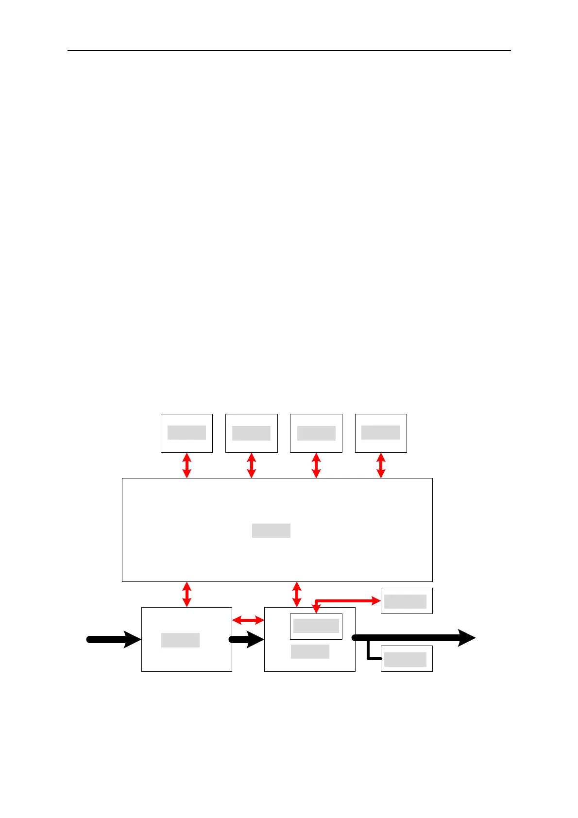
Figure 6-1 shows the system diagram.
D Board
K Board G Board
I Board
A Board
B Board
M Board
S Board
N Board
C Board
INPUT
OUTPUT
Figure 6-1
6-1

 Loading...

