Manual Operation
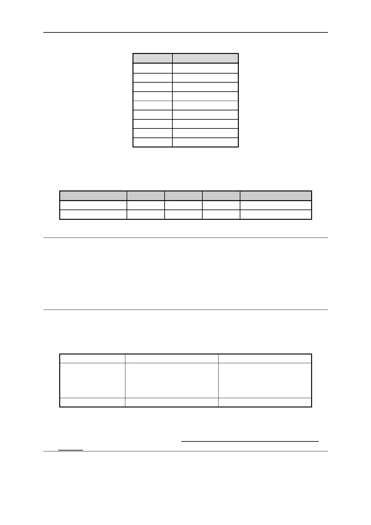
PIN NO. PIN DEFINITION
12 TTL0
13 TTL1
14 TTL2
15 TTL3
16 TTL4
17 TTL5
18 TTL6
19 TTL7
20 GND
Table 3-1
3. TTL is digital signal, which is positive logic system (5V system).
The table shows the output specification.
OUTPUT STATE MIN MIN MAX CURRENT
H (HIGH)
4.18
4.80V 7mA (Source)
L (LOW) 0.16V 0.26V -7mA (Sink)
Table 3-2
3.3.3 SERIES/PARALLEL
62000P Series DC Power Supplies are able to operate in series or parallel. Take example by
62012P-80-60, the voltage is up to 400V if connecting 5 sets in series, and the current is up to
300A if connecting 5 sets in parallel.
NOTICE
1. Series/Parallel cannot be mixed in use.
2. Table 3-2 lists the maximum numbers in series/parallel operation for 62000P Series
Power Supplies.
62000P Series Max. in Series Max. in Parallel
62012P-80-60
62012P-100-50
62012P-30-160
62006P-100-25
5 5
62012P-600-8 2 5
Table 3-3
3. When the 62000P is set to series operation, different models can be operated in series;
however, if it is set to parallel operation,
different model is unable to be operated in
parallel.
3-17

 Loading...
