Manual Operation
3.3.7.5.2 SETUP
123456
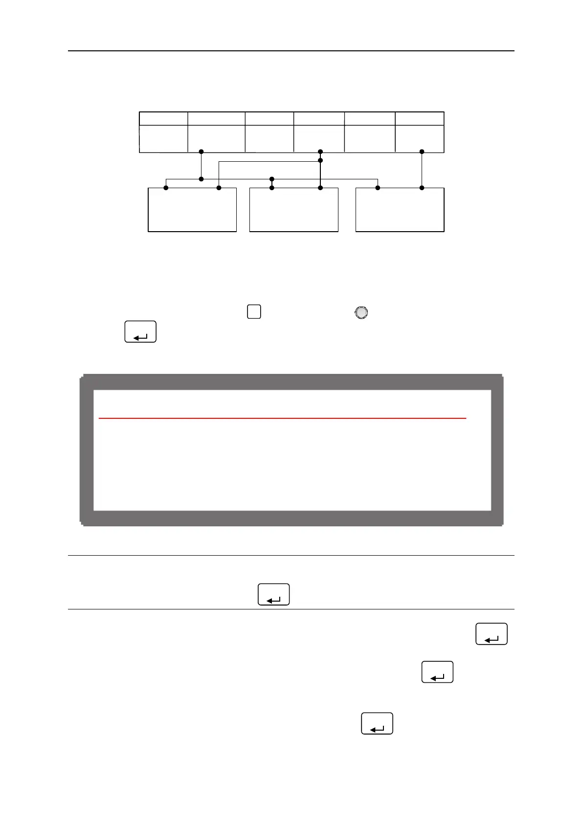
+12VA APIGND V SET I SET V
MEAS.
I
MEAS.
+
DC Power
Supply
DVM1 DVM2
− +
Figure 3-100
3.3.7.5.3 Calibration Procedure (Example: Model 62012P-80-60)
(1) In CALIBRATION page, press “
4
” or turn “Rotary” (
) knob to set CHOICE = 4.
(2) Press “
ENTER
” to confirm entering into APG Voltage Calibration options as Figure 3-101
shows.
[APG CU
RENT CAL I B
T I O N ]
C H E C
A P G C O N N E C T I O N A N D P
ESS [ E N T E
]
( S E T ) I N P U T V O L T A G E F O R S E T T I N G = 0 . 5
C T U
L A P G I N P U T V O L T A G E = 0 . 6 6 V
( S E T ) I N P U T V O L T A G E F O R S E T T I N G = 8 . 0
C T U
L A P G I N P U T V O L T A G E = 8 . 6 8 V
Figure 3-101
NOTICE
When entering into the CALILBRATION page, be sure to check the interface connection on
the rear panel is correct and then press “
ENTER
” to start calibration.
(3) When in the APG Current Calibration pages and the connection is correct, press “
ENTER
”
to confirm.
(4) It will ask users to input about 0.5V voltage signal (Pin 4), and press “
ENTER
” the cursor
will stop at position [1] as Figure 3-102 shows. Adjust the Power Supply to 0.5V±0.2V
and use DVM1 to measure the reading of Power Supply. Input the voltage (2 digits after
decimal point) read by DVM 1 to position [1] and press “
ENTER
” to confirm.
3-61

 Loading...

