Programmable DC Power Supply 62000P Series Operating & Programming Manual
[APG CU
RENT
ALI B
T I O N ]
C H E C
A P G
O N N E C T I O N A N D P
E S S [ E N T E
]
( S E T ) I N P U T V
L T A G E F O R S E T T I N G = 0 . 5
C T U
L A P G I N P U T V
L T A G E = 0 . 6 6 V
( S E T ) I N P U T V
L T A G E F O R S E T T I N G = 8 . 0
C T U
L A P G I N P U T V
L T A G E = 8 . 6 8 V
]1[
]2[
Figure 3-102
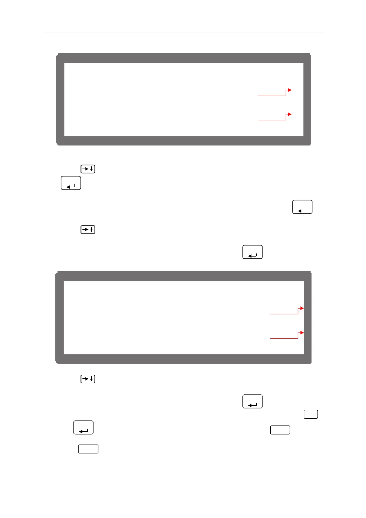
(5) Press “
” again will ask users to input about 8.0V voltage signal (Pin 4), and press
“
ENTER
” the cursor will stop at position [2] as Figure 3-102 shows. Adjust the Power
Supply to 8V±0.2V and use DVM1 to measure the reading of Power Supply. Input the
voltage (2 digits after decimal point) read by DVM 1 to position [2] and press “
ENTER
”
to confirm.
(6) Press “
” again the system will set the output voltage of Pin 6 on the rear panel to
0.5V. The cursor stops at position [3] as Figure 3-103 shows. Input the voltage (2 digits
after decimal point) read by DVM 2 to position [3] and press “
ENTER
” to confirm.
[APG CUR
ENT
AL I B
T I
N ]
H E C
PG
N N E C T I
NANDP
ESS [ E N T E
]
( M E
S . ) O U P U T
LT
GE F
MEASU
E = 0 . 5 V
AC T U A L APG
UPUT
OLT
G E = 0 . 6 6 V
( M E
S . ) O U P U T
LT
GE F
MEASU
E = 8 . 0 V
AC T U A L APG
UPUT
OLT
G E = 7 . 6 6 V
]3[
]4[
Figure 3-103
(7) Press “
” again the system will set the output voltage of Pin 6 on the rear panel to
8.0V. The cursor stops at position [4] as Figure 3-103 shows. Input the voltage (2 digits
after decimal point) read by DVM 2 to position [4] and press “
ENTER
” to confirm.
(8) The APG Voltage calibration is done once the above actions are completed. Press “
SAV E
”
and “
ENTER
”to save the calibrated data as Figure 3-95 shows, or press “
EXIT
” to return
to Calibration page without saving.
(9) Press “
EXIT
” to return to MAIN PAGE.
3-62
 Loading...


