Manual Operation
8. Press “
EXIT
” to return to MAIN PAGE.
NOTICE
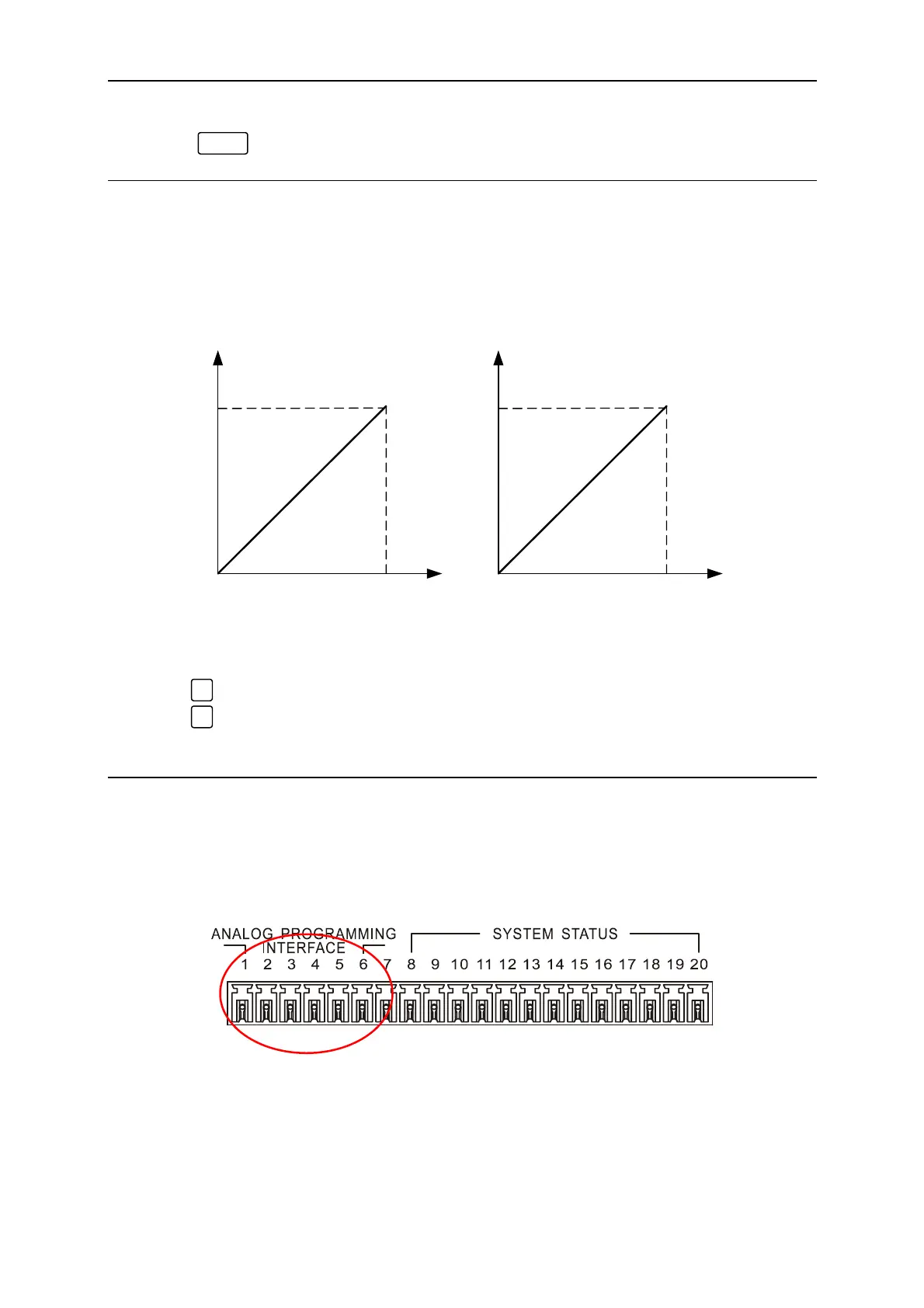
1. APG has two reference voltage level: V_ref(V)=5 / 10
a. When selecting Vref=5V
¨ it means the DC Power Supply’s output 0V/0A~80V/60A
will map to 0~5V (programming or measurement) as Figure 3-8(a) shows.
b. When selecting Vref=10V
¨ it means the DC Power Supply’s output
0V/0A~80V/60A will map to 0~10V (programming or measurement) as Figure 3-8(b)
shows.
APG INPUT 5V/5V
DC SOURCE OUTPUT
80V/60A
APG INPUT 10V/10V
DC SOURCE OUTPUT
80V/60A
(a) (b)
Figure 3-8
2. Short key description:
a. “
0
” = 5V
b. “
1
” = 10V
3. To prevent big error from occurring, it is suggested to calibrate the APG settings and
measurement before using it.
3.3.1.3.1 Pin Assignment of APG Control
APG control is an output of external analog signal and its connector is located at the rear
panel and its pin assignments are shown as Figure 3-9 and 3-10.
Figure 3-9
3-7

 Loading...

