Manual Operation
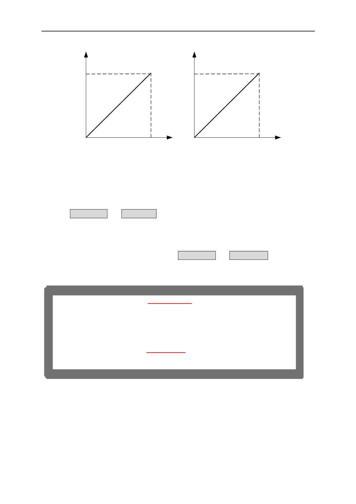
APG INPUT 5V/5V
DC SOURCE OUTPUT
400V/60A
APG INPUT 10V/10V
DC SOURCE OUTPUT
400V/60A
(a)
(b)
Figure 3-47
3.3.3.6.2 Parallel Setting
To connect 5 62012P-80-60 DC Power Supplies in parallel for operation and set the APG
option to APG = V &I and Vref(V) = 5, the MAIN PAGE of MASTER will show as Figure
3-48.
As to the voltage setting, the inputted analog voltage 0~5 V maps to the actual output 0~80 V;
and for current the inputted analog voltage 0~5 V maps to the actual output 0~300 A as
Figure 3-49(a) shows. Set the APG option to APG = V &I and Vref(V) = 10 means the
inputted analog voltage 0~10 V maps to the actual output 0~80 V for voltage also maps to the
actual output 0~300 A for current as Figure 3-49(b) shows.
V _ S E T = 2 0 . 0 0 V
I_SET=300.00A
M
S T
O F F
0 0 . 0 0 V 00 . 00A
0 . 0 W
AP
-
&I
Figure 3-48
3-31

 Loading...
