What to do if Chroma Test Equipment reports Fan Fail?
W
William LewisSep 13, 2025
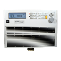
If the fan fails on your Chroma Test Equipment, it could be due to fan damage or a bad power cord connection. The suggested solution is to send the AC/DC load back to Chroma to change and check the fan.