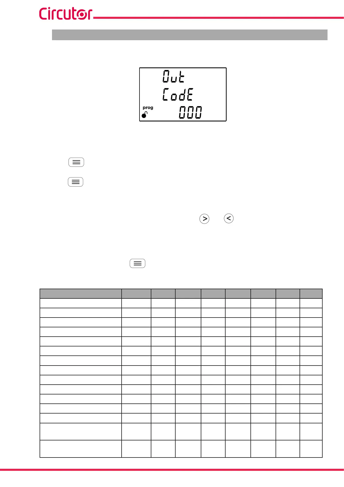
6.18.- PROGRAMMING ALARM : DIGITAL OUTPUT T1
The values corresponding to digital output T1 are programmed in this step.
The code of the variable is selected on this screen, according to Table 38, Table 39 and Table 40, which
will control digital output T1.
Press the key for 3 seconds to enter the edit mode. The prog icon will flash on the left of the
screen.
Press the key to modify the value of the flashing digit.
Set the value to 00 if you do not wish to program a variable.
When the desired value is shown on the screen, use the and keys to move the edit cursor.
If an incorrect code has been entered, the value will be deleted and the device will restore the last
value saved.
To validate the value, press the key for 3 seconds; the prog icon will stop flashing.
Table 38: Parameter codes used to program the digital output (Table 1).
Parameter Phase Code Phase Code Phase Code Phase Code
Phase-Neutral Voltage L1 01 L2 09 L3 17 - -
Current L1 02 L2 10 L3 18 - -
Active power L1 03 L2 11 L3 19 III 25
Inductive Reactive Power L1 04 L2 12 L3 20 III 26
Capacitive Reactive Power L1 05 L2 13 L3 21 III 27
Apparent power L1 06 L2 14 L3 22 III 28
Power factor L1 07 L2 15 L3 23 III 29
Cosine φ L1 08 L2 16 L3 24 III 30
% THD V L1 36 L2 37 L3 38 - -
% THD A L1 39 L2 40 L3 41 - -
Phase-Phase Voltage L1/2 32 L2/3 33 L3/1 34 - -
Frequency - 31 - - - - - -
Maximum current demand L1 45 L2 46 L3 47 - -
Active Power Maximum
Demand
- - - - - - III 42
Apparent Power Maximum
Demand
- - - - - - III 43
68
CVM-E3-MINI
Instruction Manual