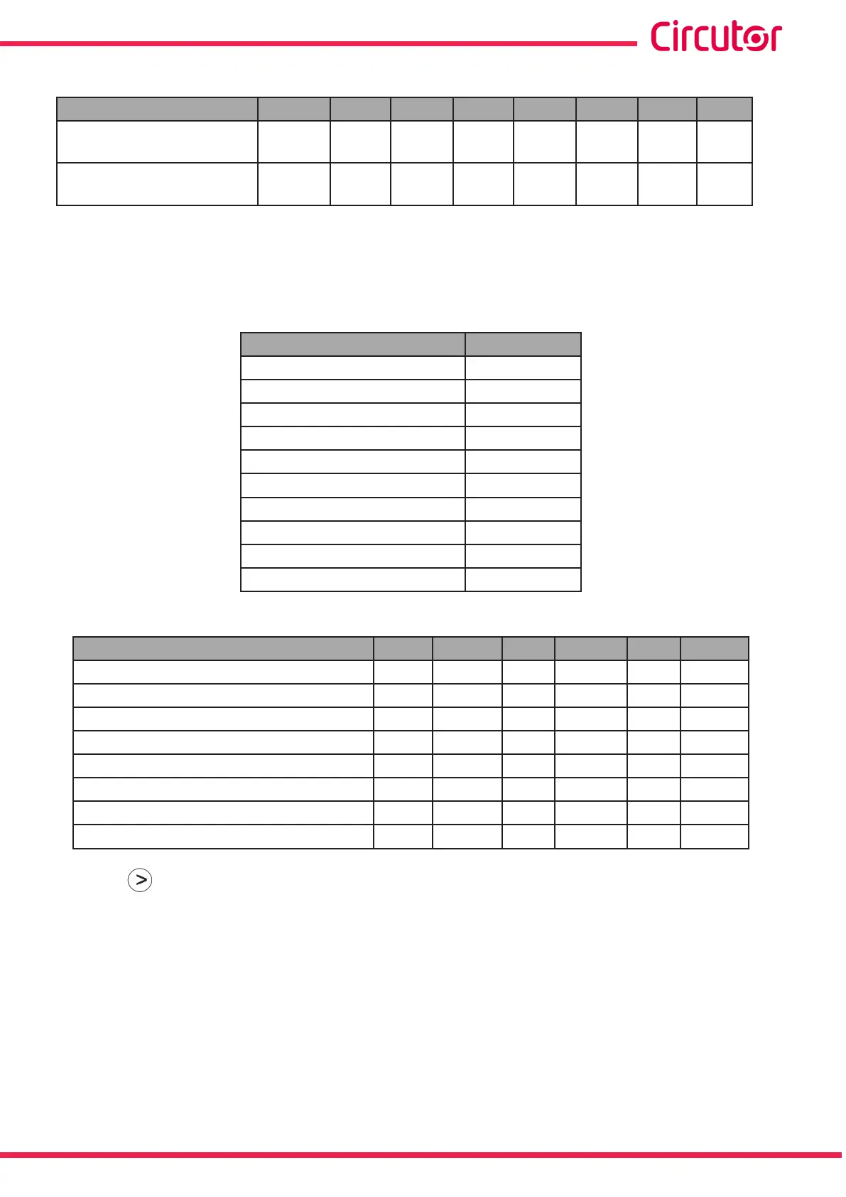
Table 38 (Continuation): Parameter codes used to program the digital output (Table 1).
Parameter Phase Code Phase Code Phase Code Phase Code
Inductive Power Maximum
Demand
- - - - - - III 132
Capacitive Power
Maximum Demand
- - - - - - III 133
In addition, there are some parameters (Table 14) that refer to the three phases at the same time (OR
function). If you have selected one of these variables, the alarm will be activated when any of the three
phases meets the programmed conditions.
Table 39: Parameter codes used to program the digital output (Table 2).
Types of parameters Code
Phase-Neutral Voltage 200
Current 201
Active power 202
Inductive Reactive Power 203
Capacitive Reactive Power 204
Power factor 205
Phase-Phase Voltage 206
% THD V 207
% THD A 208
Apparent Power 209
Table 40: Parameter codes used to program the digital output (energy pulses) (Table 3).
Parameter Tariff Code Tariff Code Tariff Code
Consumed active energy T1 49 T2 70 total 112
Generated active energy T1 59 T2 80 total 122
Consumed inductive reactive energy T1 51 T2 72 total 114
Generated inductive reactive energy T1 61 T2 82 total 124
Consumed capacitive reactive energy T1 53 T2 74 total 116
Generated capacitive reactive energy T1 63 T2 84 total 126
Consumed apparent energy T1 55 T2 76 total 118
Generated apparent energy T1 65 T2 86 total 128
Press key to access the next programming step.
If a parameter has been selected from Table 38 or Table 39, the next setup screen will be shown in
section “6.18.1. MAXIMUM VALUE”.
If a parameter has been selected from Table 40, the next setup screen will be shown in section “6.18.8.
KILOWATTS PER PULSE”.
69
Instruction Manual
CVM-E3-MINI