EasyManuals Logo

Cisco ASR 5000 Series User Manual

Cisco ASR 5000 Series
992 pages
To Next Page IconTo Next Page
To Previous Page IconTo Previous Page
Page #102 background imageLoading...
Page #102 background image
ASR 5000 Hardware Platform Overview
â–€ ASR 5000 Line Cards
â–„ Cisco ASR 5000 Series Product Overview
OL-22938-02
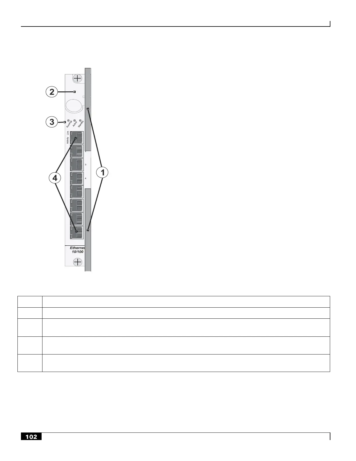
Figure 20. Ethernet 10/100 Line Card
Table 14. Ethernet 10/100 Line Card Callout Definitions
Number
Description
1
Card Ejector Levers—Use to insert/remove card to/from chassis.
2
Interlock Switch—When pulled downward, the interlock switch notifies the system to safely power down card
prior to removal.
3
Card Level Status LEDs—Show the status of the card. (See Applying Power and Verifying Installation for
definitions).
4
RJ-45 10/100 Ethernet Interfaces—Eight auto-sensing RJ-45 interfaces for R-P interface connectivity, carrying user
data. Ports are numbered 1 through 8 from top to bottom.

Table of Contents

Other manuals for Cisco ASR 5000 Series

Questions and Answers:

Question and Answer IconNeed help?

Do you have a question about the Cisco ASR 5000 Series and is the answer not in the manual?

Cisco ASR 5000 Series Specifications

General IconGeneral
BrandCisco
ModelASR 5000 Series
CategoryNetwork Router
LanguageEnglish

Related product manuals