Redundancy and Availability Features
Service Availability Features ▀
Cisco ASR 5000 Series Product Overview ▄
Hardware Redundancy Configuration
The maximum redundant configuration for a fully loaded system supporting data services consists of the following:
2 SMCs: 1 active and 1 standby (redundant)
14 processing cards: 13 active and 1 standby
2 SPIOs: 1 active and 1 standby
26 Ethernet/Gigabit Ethernet line cards: 13 active and 13 standby (10/100 Ethernet Line Card (FELC), 1000
Gigabit Line Card (GELC), and Quad Gigabit Ethernet Line Card (QGLC))
2 1000 Gigabit Ethernet Line Cards (XGLC): 1 active, 1 standby. Note that the XGLC, which is a full-height
line card that populates both the upper and lower slots of the chassis, uses a side-by-side redundancy scheme.
Refer to the Hardware Installation and Administration Guide for more information.
26 Optical (ATM) line cards: 13 active and 13 standby (OLC and OLC2)
26 Channelized line cards: 13 active and 13 standby (CLC and CLC2)
2 RCCs: 2 standby
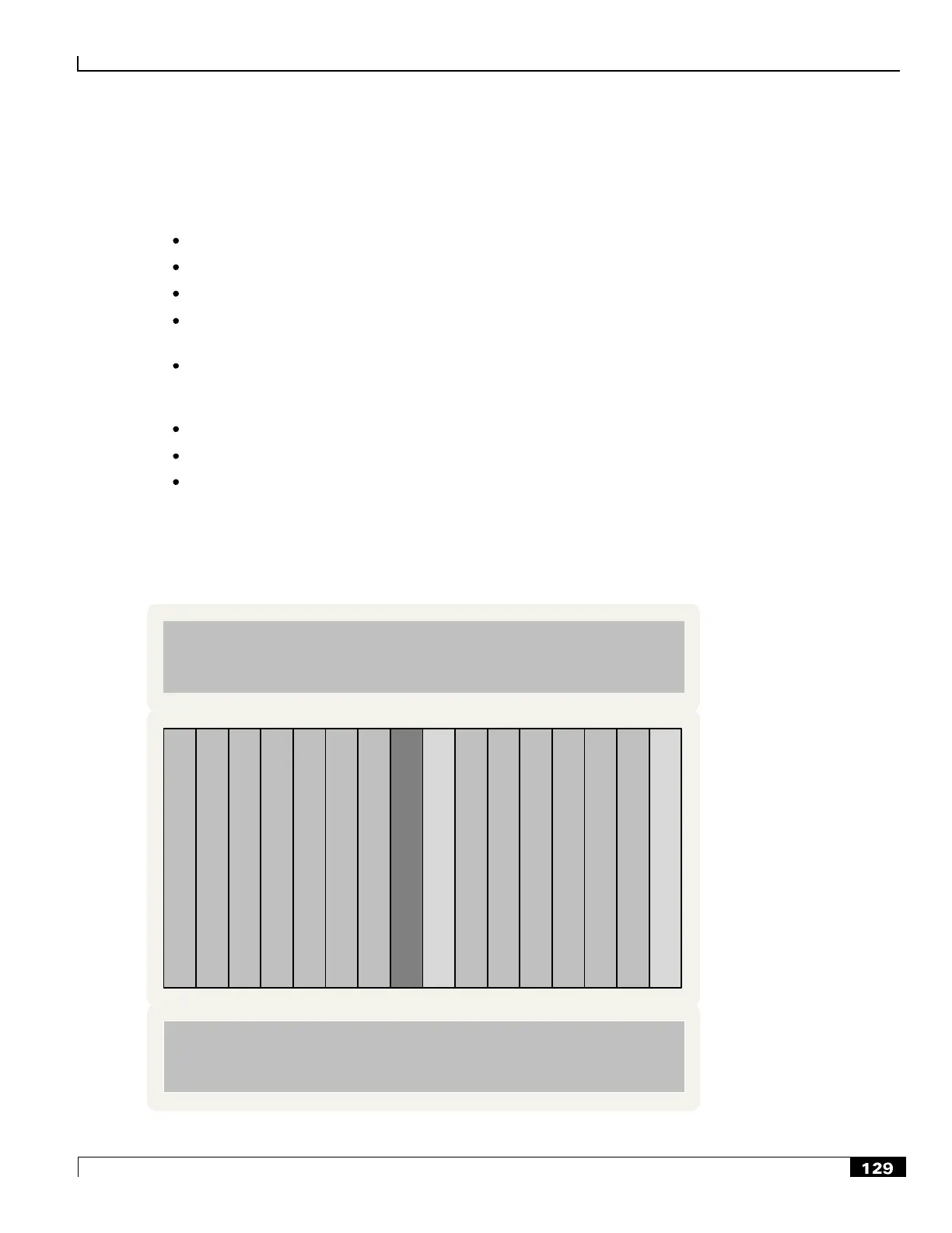
This configuration allows for the highest session capacity while still providing redundancy. The following figures depict
this recommended maximum redundant configuration.
Figure 30. Recommended Redundant Configuration for Data Services - Front View
S
t
a
n
d
b
y
P
r
o
c
C
a
r
d
S
t
a
n
d
b
y
S
M
C
A
c
t
i
v
e
S
M
C
1 3 1615141312111092 4 5 76 8
Lower Fan Tray Assembly
and Particulate Air Filter
Upper Fan Tray Assembly
Active Processor
Cards
Active Processor
Cards
 Loading...


