Packet Data Interworking Function Overview
▀ Features and Functionality - Licensed Enhanced Feature Support
▄ Cisco ASR 5000 Series Product Overview
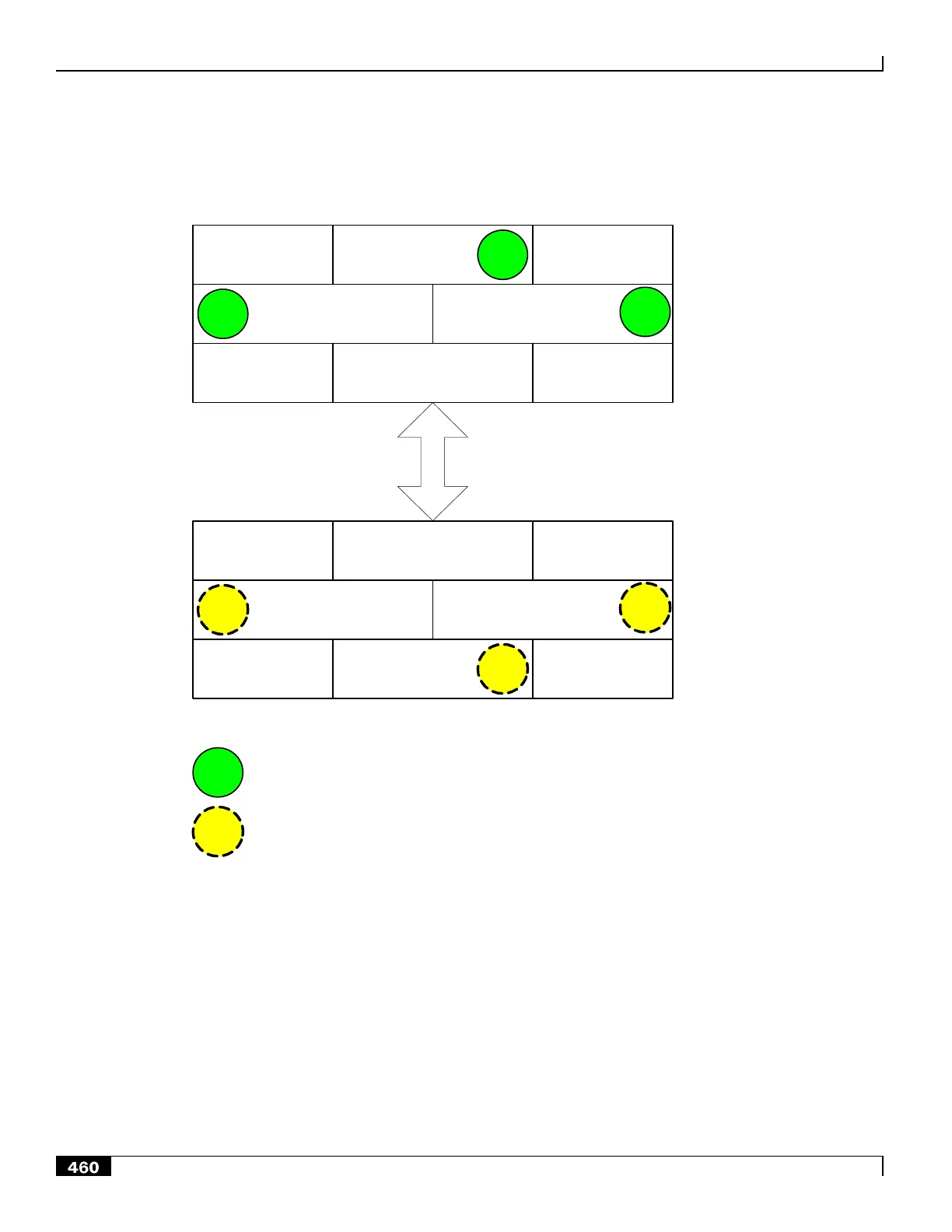
Figure 124. Loopback Interface Configuration
Primary PDIF Chassis
AAA
Context
I/F
C
Ingress
Context
I/F
A
Egress
Context
I/F
B
SRP
Context
SRP Link
AAA
Context
I/F
C
Ingress
Context
I/F
A
Egress
Context
I/F
B
SRP
Context
I/F
A
Backup PDIF Chassis
I/F
A
Active SRP – Activated loopback interface
Standby SRP – Activated loopback interface
Operation Over a Common IPv4 Network
The PDIF supports L2 switching to enable carriers not using dynamic routing between the core nodes to perform an
online upgrade.
In the example below, the SRP virtual MAC address is configured for the SRP-activated loopback address for the
subnet. This allows the standby chassis to seamlessly assume the active role in the network after a switchover. Attached
devices continue to send to the same SRP virtual MAC address and the currently active chassis responds to ARP
requests for the shared loopback IP address. This scheme allows fast standby-to-active transitions, since the SRP virtual
MAC address does not change during the switchover.

 Loading...


