▀ Interface Specifications
▄ Cisco ASR 5000 Series Product Overview
Electrical Characteristics
Each of the three dry-contact relay switches is rated to support a maximum switching current of 1A@30VDC.
Central Office Alarm Wiring Example
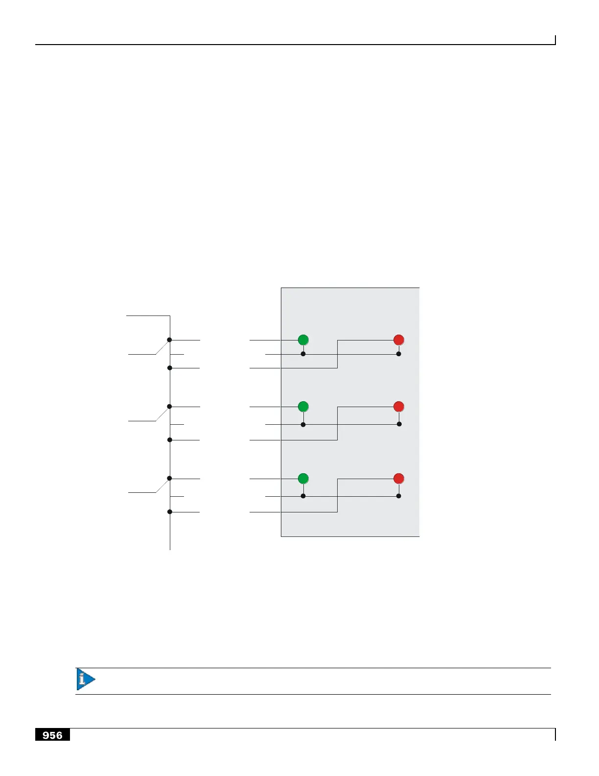
The example in the following figure shows how each of the three dry-contact relay switches can control up to two
alarming devices. In this example, the CO alarm interface is connected to a CO alarms panel. A green LED is wired to
indicate a normal condition (normally closed relay). A red LED is wired to indicate an alarm condition (normally open
relay).
Figure 224. CO Alarm Wiring Example
Pin 1 NC
SPIO CO Alarm
Interface
Pin 3 NO
Pin 4 NC
Pin 6 NO
Pin 7 NC
Pin 8 Common
Pin 9 NO
Major
Alar
m
Critical
Alarm
Minor
Alar
m
CO Alarms Panel
Pin 2 Common
Pin 5 Common
Normal Alarm
In this wiring example, with each relay switch in its NC position, the green LED is illuminated. If a relay switch were in
the NO position, the red LED would be illuminated.
BITS Timing Interface
Important: This interface is not used on SPIOs when the system is configured to perform data services.

 Loading...


