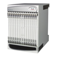
ASR 5000 Hardware Platform Overview
Cisco ASR 5000 Series Product Overview ▄
Each CLC2 provides four optical fiber physical interfaces (ports). The ports are populated by a Small Form-factor
Pluggable (SFP) modules which include an LC-type connector. The ports of the CLC2 supports two types of SFP
modules and cabling, as shown in the following table.
SFP Modules supported by the Channelized Line Card
Single-mode
Optical Fiber
Channelized (STM-1/OC-3)
SM IR-1
Single-mode Fiber, LC duplex
female connector
Fiber Types: Single-mode
optical fiber
Wavelength: 1310 nm
Core Size: 9 micrometers
Cladding Diameter: 125
micrometers
Range: Intermediate/21
kilometers
Attenuation: 0.25 dB/KM
Min/Max Tx Power: -15 dBm/-
8 dBm
Rx Sensitivity: -28 dBm
Channelized (STM-1/OC-3)
Multi-Mode
Multi-mode Fiber, LC duplex
female connector
Fiber Types: Multi-mode
optical fiber
Wavelength: 1310 nm
Core Size: 62.5 micrometers
Cladding Diameter: 125
micrometers
Range: Short/2 kilometers
Min/Max Tx Power: -19 dBm/-
14 dBm
Rx Sensitivity: -30 dBm
Install the CLC/CLC2 directly behind its respective (Active) packet processing card. You may optionally install
CLCs/CLC2s behind a redundant (Standby) packet processing card. As with other line cards, install the Channelized
Line Cards in slots 17 through 23, 26 through 39, and 42 through 48.
The following figures show the panel of the CLC and CLC2 Channelized Line Cards, identifying their interfaces and
major components.

 Loading...


