▀ How the PDN Gateway Works
▄ Cisco ASR 5000 Series Product Overview
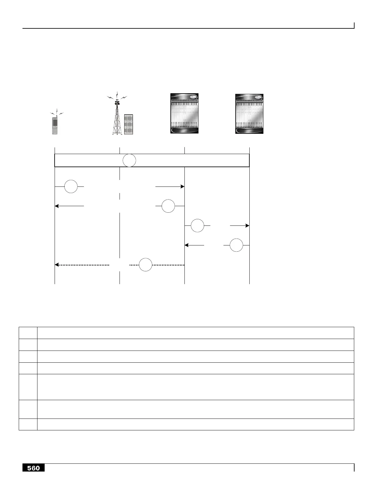
Figure 138. PDN Connection Release by the UE Call Flow
eAN/ePCF HSGW (MAG) P-GW (LMA)UE
PPP VSNCP-Term-Req
3
Attached
1
2
PPP VSNCP-Term-Ack
4
PBU
5
PBA
6
RA
Table 74. PDN Connection Release by the UE Call Flow Description
The UE is attached to the EPC and has a PDN connection with the P-GW for PDN-ID=x and APN with assigned HNP.
The UE decides to disconnect from the PDN and sends a PPP VSNCP-Term-Req with PDNID=x.
The HSGW starts disconnecting the PDN connection and sends a PPP-VSNCP-Term-Ack to the UE (also with PDNID=x).
The HSGW begins the tear down of the PMIP session by sending a PBU Deregistration to the P-GW with the following
attributes: Lifetime=0, MNID, APN, ATT=HRPD, HNP. The PBU Deregistration message should contain all the mobility
options that were present in the initial PBU that created the binding.
The P-GW looks up the Binding Cache Entry (BCE) based on the HNP, deletes the binding, and responds to the HSGW
with a Deregistration PBA with the same attributes (Lifetime=0, MNID, APN, ATT=HRPD, HNP).
The HSGW optionally sends a Router Advertisement (RA) with assigned HNP and prefix lifetime=0.

 Loading...


