Interface Specifications ▀
Cisco ASR 5000 Series Product Overview ▄
Data Carrier Detect (DCD)
Data Terminal Ready (DTR)
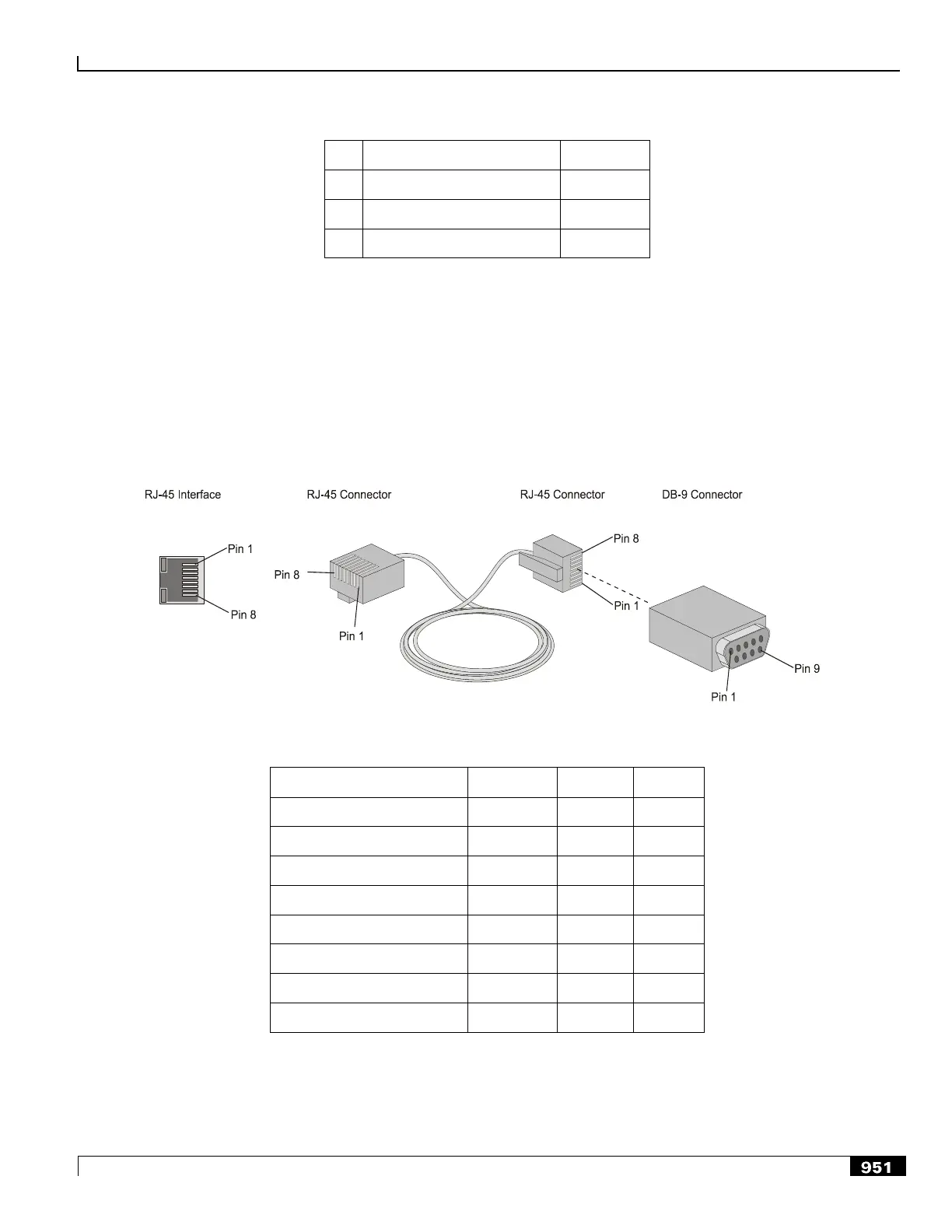
Console Cable Specifications
SPIO cards are shipped with a console cable assembly that includes a 7-foot serial cable with RJ-45 connectors on each
end, and an RJ-45-to-DB-9 adapter. Use the RJ-45-to-DB-9 adapter to connect the console cable to a terminal server or
terminal emulation device such as a laptop computer. The cable‘s pin-out is provided in the following figure and table.
Figure 219. SPIO Console Cable Assembly
Table 106. RJ-45 to DB-9 Cable
Data Carrier Detect (DCD)
Data Terminal Ready (DTR)
To construct a RJ-45 to DB-25 cable for modem connectivity, refer to the table that follows.

 Loading...


