B-11
Catalyst 2950 Desktop Switch Hardware Installation Guide
78-11157-05
Appendix B Connectors and Cables
Cable and Adapter Specifications
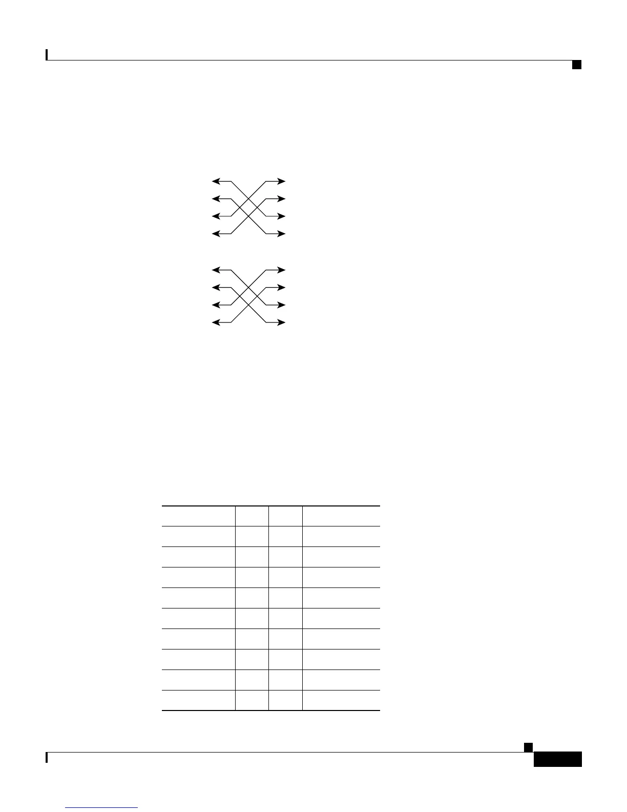
Figure B-13 Four Twisted-Pair Crossover Cable Schematics for 10/100/1000 and
1000BASE-T GBIC Module Ports
RJ-21 Cable Pinouts
Table B-1 lists the RJ-21 cable pinouts on the Catalyst 2950ST-24 LRE and
Catalyst 2950ST-24 LRE 997 switches.
Table B-2 lists the RJ-21 cable pinouts on the Catalyst 2950ST-8 LRE switches.
1 TPO+
2 TPO-
3TP1+
6TP1-
1TP0+
Switch Switch
2TP0-
3TP1+
6TP1-
4TP2+
5TP2-
7TP3+
8TP3-
4TP2+
5TP2-
7TP3+
8TP3-
65274
Table B-1 RJ-21 Cable Pinouts on the Catalyst 2950ST-24 LRE and
Catalyst 2950ST-24 LRE 997 Switches
Function Pin Pin Function
Port 1 Tip 1 26 Port 1 Ring
Port 2 Tip 2 27 Port 2 Ring
Port 3 Tip 3 28 Port 3 Ring
Port 4 Tip 4 29 Port 4 Ring
Port 5 Tip 5 30 Port 5 Ring
Port 6 Tip 6 31 Port 6 Ring
Port 7 Tip 7 32 Port 7 Ring
Port 8 Tip 8 33 Port 8 Ring
Port 9 Tip 9 34 Port 9 Ring