Chapter 2 Overview
Front-Panel Description
2-20
Catalyst 2950 Desktop Switch Hardware Installation Guide
78-11157-05
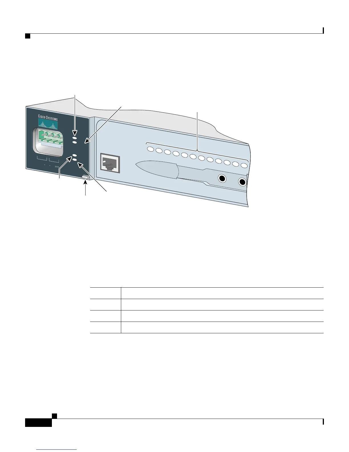
Figure 2-17 LEDs on Catalyst 2950ST-24 LRE 997 Switches
System LED
The system LED shows whether the system is receiving power and functioning
properly. Table 2-3 lists the LED colors and meanings.
For information about the system LED colors during the power-on self-test
(POST), see the “Connecting to a Power Source” section on page 1-5.
A
B
INPUT :
36 - 72 V
CURRENT
:
2 - 1 A
+
-
+
-
S
Y
S
T
R
P
S
S
TA
T
S
P
E
E
D
M
O
D
E
1
2
3
4
5
6
7
8
9
10
11
12
CONSOLE
89364
Redundant
power
system
LED
Mode
button
Speed
LED
STAT
LED
Port status
LEDs
System
LED
Table 2-3 System LED
Color System Status
Off System is not powered up.
Green System is operating normally.
Amber System is receiving power but is not functioning properly.