2-17
Catalyst 2950 Desktop Switch Hardware Installation Guide
78-11157-05
Chapter 2 Overview
Front-Panel Description
LEDs
You can use the LEDs to monitor switch activity and performance. The locations
of the LEDs vary among switch models. The Mode button that you use to select
the port mode also varies by model. See these figures:
• Figure 2-13 for the Catalyst 2950-12, 2950-24, 2950C-24, 2950SX-24, and
2950T-24 switches
• Figure 2-14 for the Catalyst 2950G-12-EI, 2950G-24-EI, and
2950G-24-EI-DC switches
• Figure 2-15 for the Catalyst 2950G-48-EI switches
• Figure 2-16 for the Catalyst 2950ST-8 LRE and 2950ST-24 LRE switches
• Figure 2-16 for the Catalyst 2950ST-24 LRE 997 switches
All of the LEDs described in this section (except the utilization meter [UTIL]) are
visible in the Cluster Management Suite (CMS). The switch software
configuration guide describes how to use CMS to configure and to monitor
individual switches and switch clusters.
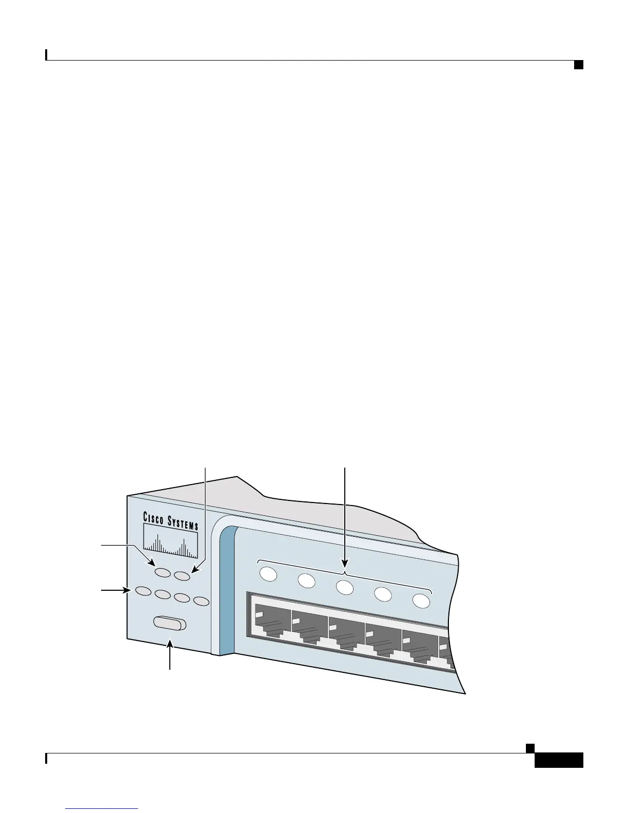
Figure 2-13 LEDs on Catalyst 2950-12, 2950-24, 2950C-24, 2950SX-24, and 2950T-24 Switches
SYST
RPS
DUPLX
MODE
SPEED
UTIL
S TAT
1x
2x
3x
4x
5x
6x
52918
Mode button
Port mode
LEDs
System
LED
Port status
LEDs
RPS
LED