EasyManuals Logo

Cisco Catalyst 2950 Hardware Installation Guide

Cisco Catalyst 2950
232 pages
To Next Page IconTo Next Page
To Previous Page IconTo Previous Page
Page #104 background imageLoading...
Page #104 background image
Chapter 3 Installation
Installing the Switch on a Wall
3-24
Catalyst 2950 Desktop Switch Hardware Installation Guide
78-11157-05
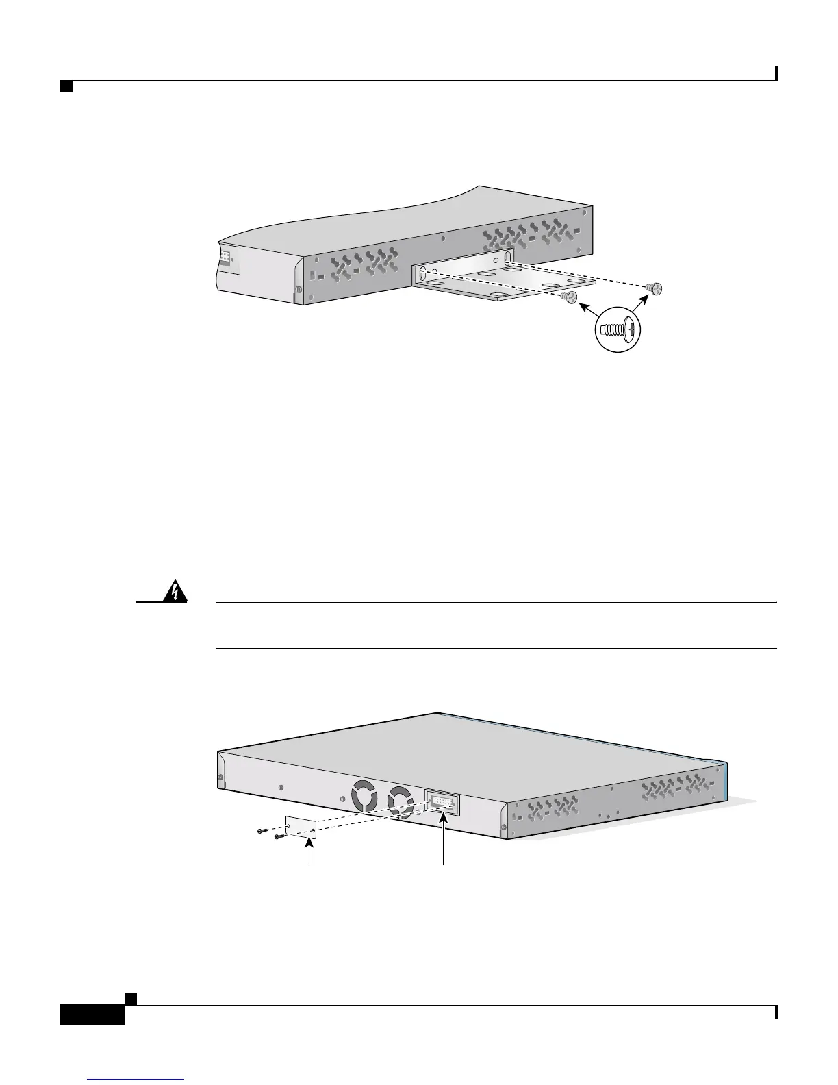
Figure 3-18 Attaching Brackets for Wall-Mounting for the Catalyst 2950 Switch
Attaching the RPS Connector Cover
If you are not using a redundant power system (RPS) with your switch, use two
number-4 Phillips pan-head screws to install an RPS connector cover to the back
of the switch. (See Figure 3-19.) The pan-head screws are included in the
accessory kit.
Warning
If an RPS is not connected to the switch, install an RPS connector cover on the
back of the switch.
Figure 3-19 Attaching the RPS Connector Cover
47303
Phillips
truss-head
screws
RPS
connector cover
RPS
connector
86310

Table of Contents

Other manuals for Cisco Catalyst 2950

Questions and Answers:

Question and Answer IconNeed help?

Do you have a question about the Cisco Catalyst 2950 and is the answer not in the manual?

Cisco Catalyst 2950 Specifications

General IconGeneral
Forwarding Bandwidth8.8 Gbps
Switching Capacity13.6 Gbps
Forwarding Rate6.6 Mpps
Weight3.6 kg
RAM16 MB
Flash Memory8 MB
Operating Humidity10% to 85% non-condensing
Uplink Ports2 x 10/100/1000Base-T
Dimensions4.4 cm x 44.5 cm x 24.2 cm
Remote Management ProtocolSNMP, Telnet, HTTP
FeaturesQuality of Service (QoS), VLAN support
Compliant StandardsIEEE 802.3, IEEE 802.3u, IEEE 802.1D, IEEE 802.1Q, IEEE 802.1p
Status Indicatorssystem
Operating Temperature0 to 45°C
Ports24 x 10/100 Ethernet ports
MAC Address Table Size8, 192 entries
Power SupplyInternal 100-240V AC, 50-60Hz

Related product manuals