Chapter 3 Installation
Where to Go Next
3-50
Catalyst 2950 Desktop Switch Hardware Installation Guide
78-11157-05
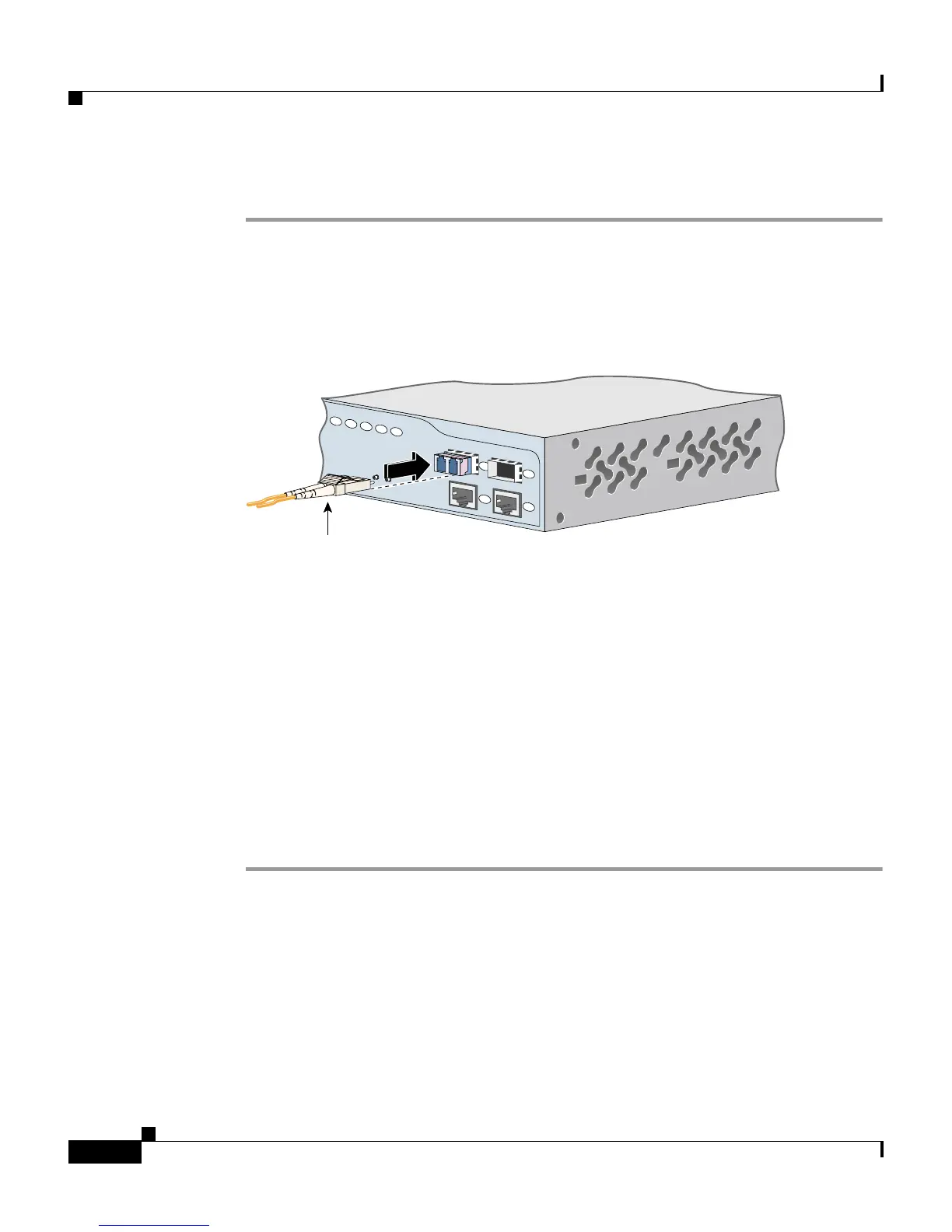
Follow these steps to connect a fiber-optic cable to an SFP module:
Step 1 Remove the rubber plugs from the module port and fiber-optic cable, and store
them for future use.
Step 2 Insert one end of the fiber-optic cable into the SFP module port (see Figure 3-41).
Figure 3-41 Connecting to an SFP Module Port
Step 3 Insert the other cable end in a fiber-optic receptacle on a target device.
Step 4 Observe the port status LED.
The LED turns green when the switch and the target device have an established
link.
The LED turns amber while the STP discovers the network topology and searches
for loops. This process takes about 30 seconds, and then the port LED turns green.
If the LED is off, the target device might not be turned on, there might be a cable
problem, or there might be problem with the adapter installed in the target device.
See Chapter 3, “Troubleshooting,” for solutions to cabling problems.
Step 5 If necessary, reconfigure and restart the switch or target device.
Where to Go Next
For information about starting up the switch, see Chapter 1, “Quick Installation.”
For information about configuring the switch, refer to the switch software
configuration guide.
19
20
21
22
23
24
2
1
Catalyst 2950
SERIES
LRE
2
1
Cable
81568