B-5
Catalyst 2950 Desktop Switch Hardware Installation Guide
78-11157-05
Appendix B Connectors and Cables
Connector Specifications
Figure B-2 RJ-45 Pinouts for 10/100/1000 and 1000BASE-T GBIC Module Ports
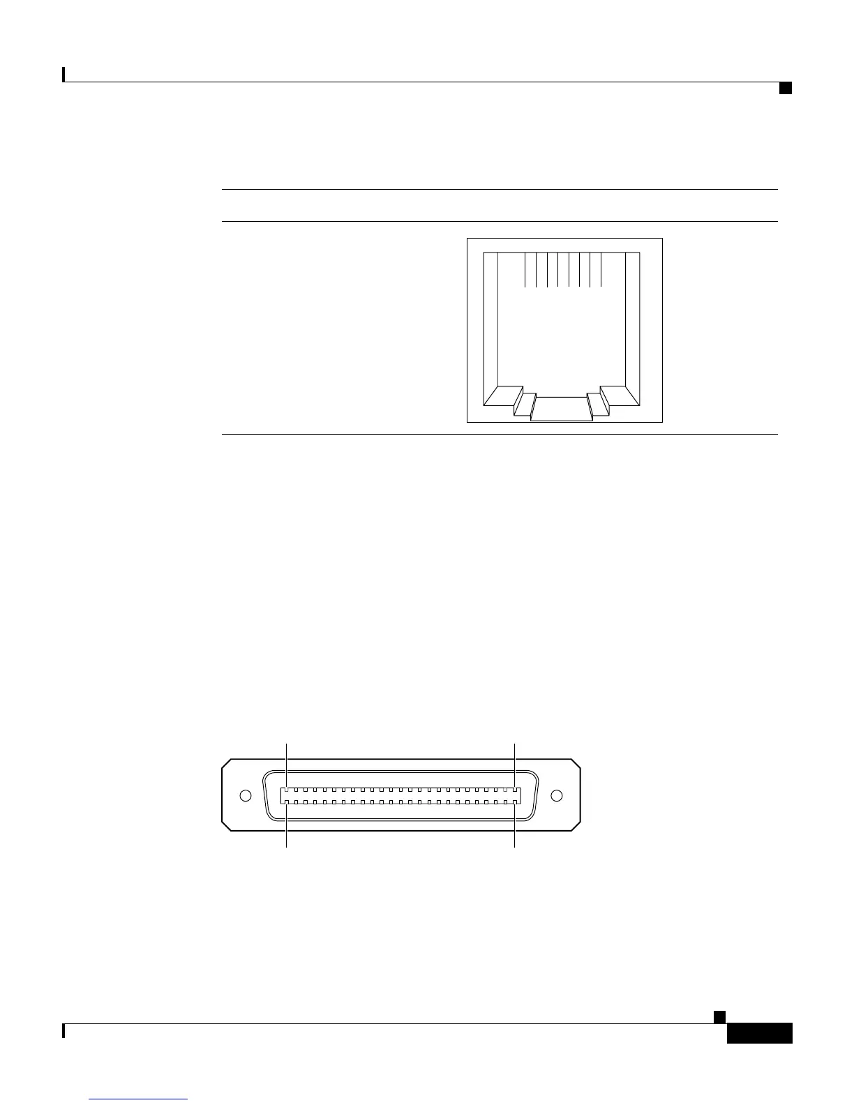
LRE Port
The LRE port uses a single 50-pin RJ-21 connector, as shown in Figure B-3. Each
LRE port uses two pins. Because the Catalyst 2950ST-24 LRE and
Catalyst 2950ST-24 LRE 997 switches use 48 pins, pin 25 on the top row and
pin 50 on the bottom row are not used
The Catalyst 2950ST-8 LRE switch uses only 16 pins. Pins 9 through 25 on the
top row and pins 34 through 50 on the bottom row are not used.
Figure B-3 RJ-21 Connector
1 2 3 4 5 6 7 8
Pin Label
1
2
3
4
5
6
7
8
TP0+
TP0-
TP1+
TP2+
TP2-
TP1-
TP3+
TP3-
34751
1
26
25
50
17093