2-25
Catalyst 2950 Desktop Switch Hardware Installation Guide
78-11157-05
Chapter 2 Overview
Front-Panel Description
For more information about GBIC LEDs, refer to your GBIC module
documentation.
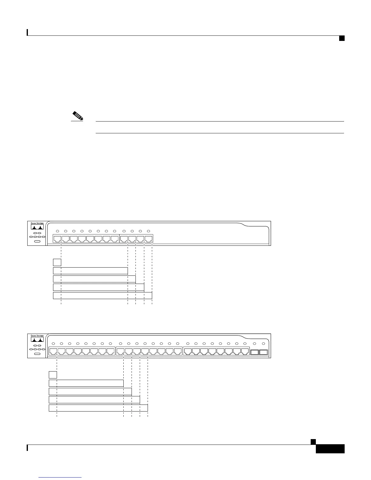
Figure 2-18 to Figure 2-22 show the bandwidth utilization percentages displayed
by the right-most LEDs.
Note The Catalyst 2950 LRE switch LEDs do not give utilization status.
If all LEDs on a Catalyst 2950-12, 2950-24, 2950C-24, 2950SX-24, or 2950T-24
switch are green (no amber showing), the switch is using 50 percent or more of
the total bandwidth. If the far-right LED is off, the switch is using more than 25
but less than 50 percent of the total bandwidth, and so on. If only the far-left LED
is green, the switch is using less than 0.0488 percent of the total bandwidth. (See
Figure 2-18 and Figure 2-19.)
Figure 2-18 Bandwidth Utilization on Catalyst 2950-12 Switches
Figure 2-19 Bandwidth Utilization on Catalyst 2950-24, 2950C-24, 2950SX-24, and 2950T-24 Switches
1x 2x 3x 4x 5x 6x 7x 8x 9x 10x 11x 12x
SYST RPS
DUPLX
MODE
SPEEDUTILSTAT
Catalyst 2950 SERIES
10Base-T / 100Base-TX
47267
6.25–12.4%+
12.5–24%+
0–0.0487%+
25–49%+
50%+
1x 2x 3x 4x 5x 6x 7x 8x 9x 10x 11x 12x 13x 14x 15x 16x 17x 18x 19x 20x 21x 22x 23x 24x 25x 26x
SYST RPS
DUPLX
MODE
SPEEDUTILSTAT
Catalyst 2950 SERIES
10Base-T / 100Base-TX
100Base-FX
74725
6.25–12.4%+
12.5–24%+
0–0.0487%+
25–49%+
50%+