User Guide | FreeSpeak II™ Base station version
9.1.2 FS II transceiver/antenna connector panel
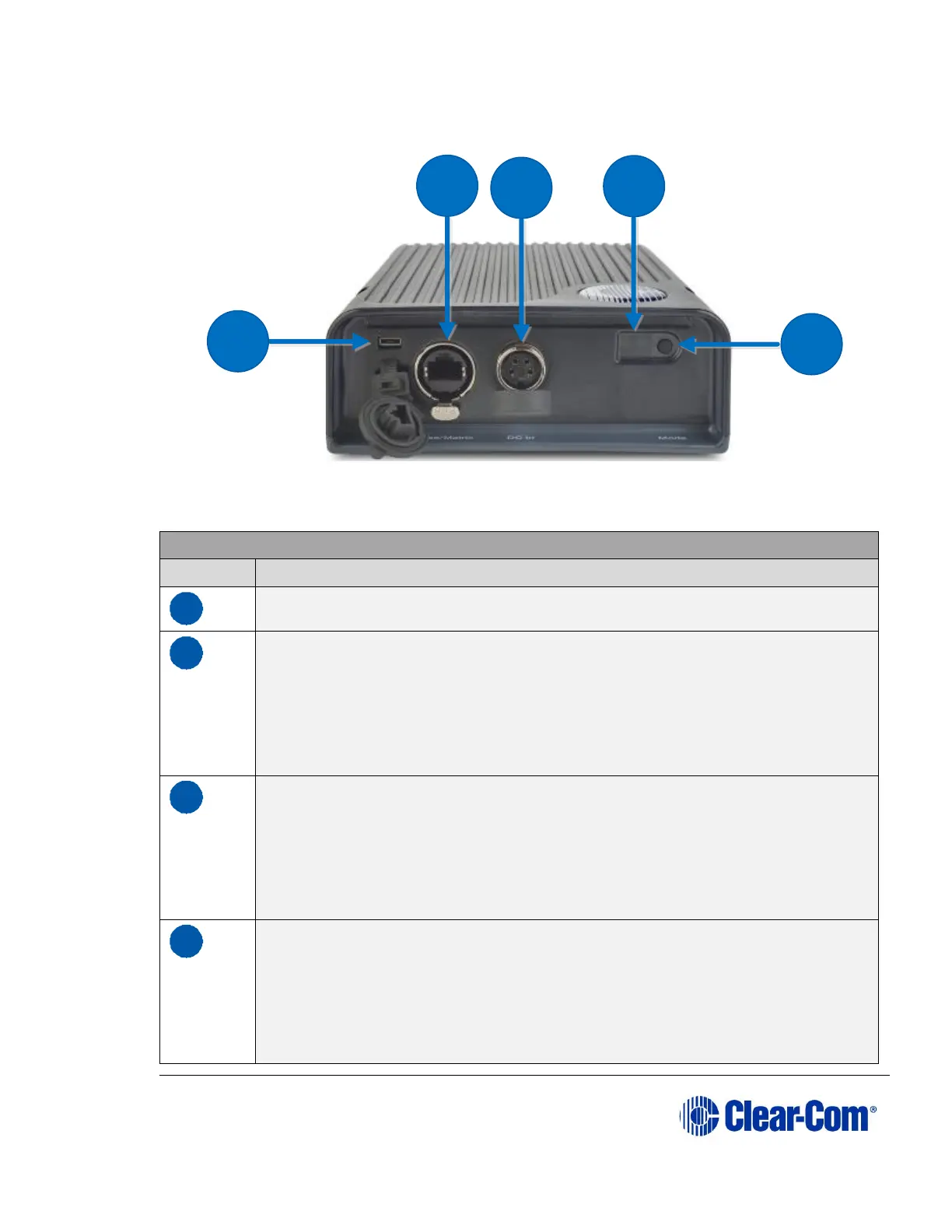
Figure 9-2 FS II Transceiver/Antenna Connector Panel
Key to transceiver/antennas
USB connector. Used to upgrade the firmware in the FS II-TA.
Base/Matrix connector. This RJ-45/etherCON connector is used to
connect the bi-directional signal from the Base station, directly or via
the splitter. Up to 1,000 meters (3,200 feet) of 4-pair 24AWG
shielded Ethernet cable (CAT5/5e/6) can be used for this connection
between Base station and transceiver/antenna. If 26AWG cable is
used the maximum distance is 500 meters (1,600 feet).
DC in power connector. This connector is used to locally power the
transceiver/antenna with the supplied universal power supply. Use of
local power is required when the transceiver/antenna is located more
than 300 meters (925 feet) from the FS II Base station or the splitter,
and is recommended even when the transceiver/antenna is closer
whenever it is available and convenient.
Data signal/Power LEDs. This amber LED indicates that a
connection has been established between the Base station and the
transceiver/antenna, and that it is actively creating a coverage zone
within which the beltpacks can operate.
A flashing amber LED indicates that a data connection has been
established with the Base station. A solid amber light shows that