User Guide | FreeSpeak II™ Base station version
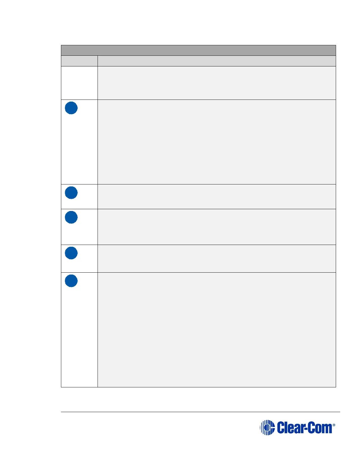
Key to FS II Base station rear panel
used to activate a
light or lock or some other device. The relay may
be wired for normally closed
or normally open operation, and the
signal appears on pins 1 & 6 or 2 & 6. It is
rated to a maximum of 30-
VDC at 1 amp.
Four-wire matrix ports
These four RJ-45 connectors can connect four full-duplex (input pair
and output
pair) audio connections from a 4-wire communications
device, digital matrix
intercom, or similar – making them available to
the wireless beltpacks. Any of
the 4-wire ports or the program input
can be assigned as IFB sources from the
front panel.
Each of these connectors has its own time slot, and can be addressed
separately from a beltpack, or combined with other beltpacks and
rear-panel
connectors in a group. Level adjustment is done via the
front-panel display
programming.
The connector has no function in FS II.
LAN connector
This RJ-45 connector allows the Base station to be connected to a LAN
for system software upgrades and configuration downloads from the
Configuration
Editor. It is a 10BaseT Ethernet port.
This female DB-9 connects to a PC computer for firmware updates and
monitoring of the system configuration. It functions as a serial port.
Transceiver connectors
These two RJ-45 connectors connect the Base station to two remote
FS-TA
transceiver/antennas or antenna splitters.
Each wired transceiver/antenna communicates with five wireless
beltpacks.
Each antenna splitter provides connection for five
transceiver antennas,
providing communication with up to a
maximum of 10 beltpacks depending
upon available bandwidth.
To meet FCC emissions requirements a ferrite must be fitted on any
CAT-5
cable plugged into either of the two ports labeled
“transceivers.” The ferrite
should be fitted at the Base station end of
the CAT-5 cable. Position the ferrite as close to the Base station as
possible. A suitable ferrite is available from Wurth, part number 742
711 32.