5-2 Desktop Removal and Replacement
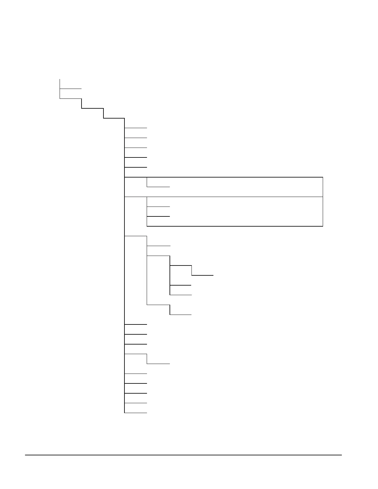
5.2 Disassembly Sequence Chart
Use the chart below to determine the disassembly sequence for removing components from the
computer.
5.3 Computer Feet
5.4 Preparation for Disassembly
5.5 Cable Lock
5.6 System Unit Cover
5.6.1 Quick Release Cover Latch
5.6.2 Power Button
5.6.3 Bezel Blank
5.7 Cover Latch Retainer
5.8 Drive Power Cables
5.9.1 Side-Mounted Hard Drive
5.10.1 3.5-Inch Drive Release Latch
5.9.2 5.25-Inch Drive
5.9.3 3.5-Inch Drive from a 5.25-inch Drive Adapter
5.10.2 5.25-Inch Drive Release Latch
5.11 Tilt Drive Cage
5.12.1 Disconnecting and Raising the Expansion Board Cage
5.12.2 Expansion Board
5.12.3 Expansion Board Cage
5.12.4 Riser Board
5.12.5 Expansion Board Cage Guide Bracket
5.12.6 Lift Lever
5.13 Expansion Board Cage Chassis-Mounted Guide Bracket
5.14.1 System Board
5.12.7 Fan
5.14.2 Microprocessor
5.14.3 Memory
5.14.4 Battery
5.15.1 AGP Graphics Board
5.15.2 Matrox Millennium II Graphics Memory
5.15.3 ATI RAGE PRO TURBO Graphics Memory
5.16 Speaker
5.17 Power Supply
5.18.1 Smart Cover Lock Solenoid
5.18.2 Power Switch Cable Assembly
✎
All drives should be removed from the drive bay before removing the drive cage
from the chassis.

 Loading...