5-40 Desktop Removal and Replacement
5.18.2 Power Switch Cable Assembly Removal
The power switch mounting bracket and status LEDs are a part of this cable assembly.
1. Prepare the computer for disassembly (Section 5.4).
CAUTION:
When the computer is plugged into an AC power source, there is always voltage applied to the
system board. You must disconnect the power cord from the power source before opening the computer
to prevent system board or component damage.
2. Remove the system unit cover (Section 5.6).
3. Disconnect the cables from the rear of all of the drives.
4. Grasp the top of the tilt drive cage and rotate it to its full upright position.
5. Remove the side mounted hard drive from the drive cage (Section 5.9.1).
6. Disconnect the power switch cable from the P5 connector 1 on the rear of the riser board.
7. Remove the cover lock solenoid from the chassis 2 (Section 5.18.1), then disconnect the power
switch cable from it.
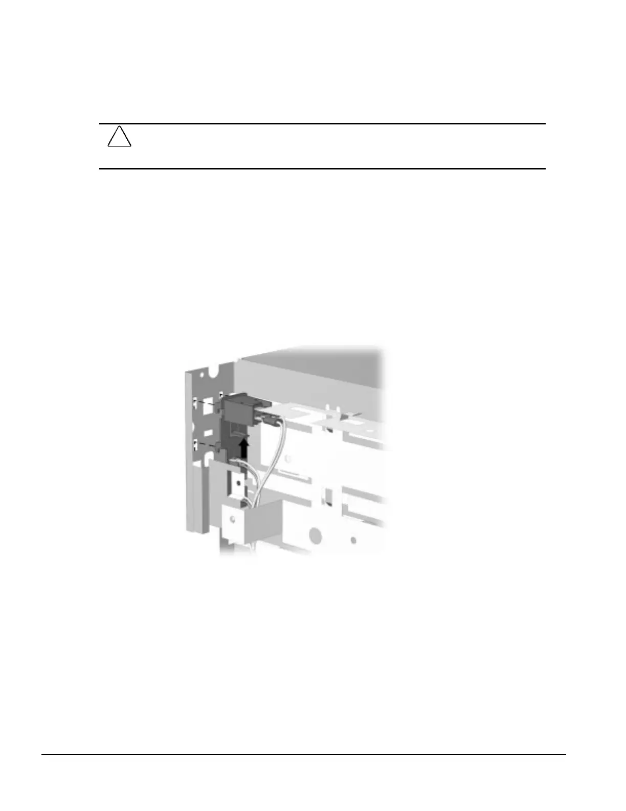
8. From the inside of the chassis, squeeze the tab on the power switch bracket holder 3 up, then
lift the assembly up 4 to release it from the chassis.
Removing the Power Switch Bracket Assembly

 Loading...