DeviceMaster Installation and Configuration Guide: 2000594 Rev. F Hardware Installation - 15
Hardware Installation
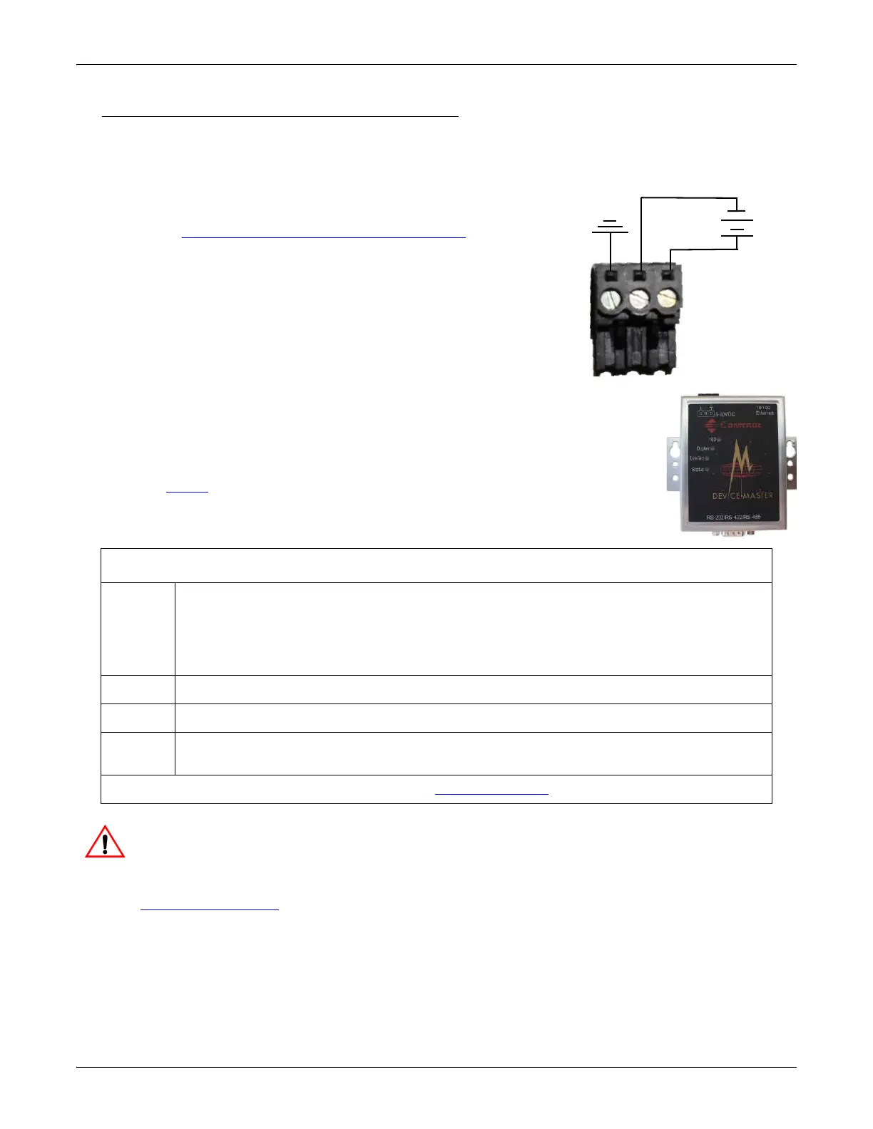
5-30VDC with Screw Terminal Power Connector
Use the following procedure power on this model.
Observe proper ESD techniques when connecting and disconnecting the DeviceMaster.
• Insert the earth ground wire into the earth ground screw terminal.
• Insert the DC positive wire into the positive screw terminal and the
DC return wire into the return screw terminal.
Refer to 1-Port Panel Mount 5-30VDC Power Supply on Page 140 for
detailed power requirements.
• Use a small flat head screw to lock the wires into place.
• Verify that each wire has been tightened securely.
• Plug the screw terminal power connector into the DeviceMaster.
Note: Align the plug properly. The scalloped side of the screw terminal power
connector should be aligned with the scalloped side of the power jack on
the unit.
• Connect the power supply to a power source.
•Go to Step 4 to verify that the DeviceMaster is functioning properly.
4. Verify that the Status LED has completed the boot cycle and network connection for
the DeviceMaster is functioning properly using the table below.
Do not connect RS-422/485 devices until the IP address is configured and an appropriate
port interface type has been configured. The default port setting is RS-232.
5. Go to Initial Configuration on Page 33 to configure the DeviceMaster for use.
1-Port Panel Mount LED Descriptions
Status
The amber Status LED on the device is lit, indicating you have power and it has
completed the boot cycle.
Note: The Status LED flashes while booting and it takes approximately 15 seconds for
the Bootloader to complete the cycle. When the Bootloader completes the cycle, the
LED has a solid, steady light that blinks approximately every 10 seconds.
Link/Act If the red Link/Act LED is lit, it indicates a working Ethernet connection.
Duplex If the red Duplex LED is lit, it indicates full-duplex activity.
100
If the red 100 LED is lit, it indicates a working 100 MB Ethernet connection (100 MB
network, only). If the LED is not lit, it indicates a 10 MB Ethernet connection.
Note: For additional LED information, go to the Status LED table on Page 148.
Earth Gnd
Return
Positive
5-30VDC
+
-
Wire gauge:
AWG 12-22