Configuration and Setup 3-13
3.5 Physical Placement of the Scanner
Please follow the guidelines below for optimal safety, scanner functionality, and scanning
results.
Physical placement of the scan station:
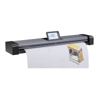
On Scanners:
Your wide format flatbed scanner should be placed on a stabile, level and completely flat
(plane) surface such as a sturdy table. If convenient, you can place the backend of the scanner
against a wall. The lid will not open all the way back and stops at an approximate 65
0
angle.
It is very important to follow the instructions below to ensure the scanner is setup with optimal
stability and without tension on the scanner’s frame. Failure to do so can produce poor
scanning results and cause damage to the scanner device over time.
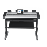
The scanner rests on feet placed at the bottom of the scanner. Some flatbed scanner models
support 4 adjustable feet while later flatbed models have 3 fixed feet and 2 adjustable feet (total
of 5 feet). See the instructions below for each type of feet-configuration.
4 feet models
1. These scanners are more sensitive to uneven surfaces and it is best to ensure that you
have a completely plane surface.
2. Position (tighten) all four feet all the way up so they all have an equal height.
3. Place the scanner on the flat surface aligned in its optimal position for usage.
4. You can make slight adjustments to the feet if necessary. Use a long object to get in
under the scanner and rotate the feet to lengthen them. Only very slight adjustments
are acceptable. If major adjustments are required, you should find another table with a
flatter surface.
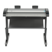
5 feet models
1. The two outer feet closest to the operator’s panel side are adjustable. The middle foot
on the same side and the two feet on the other side are fixed. See the illustration
below.
2. The 2 adjustable feet should be positioned (tightened) all the way up when setting up
the scanner on its new surface. They are delivered in that position from the
manufacturer.
3. The 2 adjustable feet (in their original position as described in step 2) are slightly
shorter than the 3 fixed feet. Therefore the scanner will at first rest only on the 3 fixed
feet (1 on the operator panel side and 2 on the opposite side).
4. Use a screwdriver or an alternative long slim object to access and rotate the 2
adjustable feet until they touch the surface so all 5 feet are in contact with it.
5. If the scanner is moved, the 2 adjustable feet must be retightened to their original
(shortest) position and the steps above must be repeated.