Technical Specifications
0 ~ 126 (setting by DIP switch)
126, up to 125 SM277 stations
Total 6, 2 reserved (1 used for PG, the other used for OP)
20.4 ~ 28.8VDC (class 2 or PLC sensor power)
Max current (Module
only with port active)
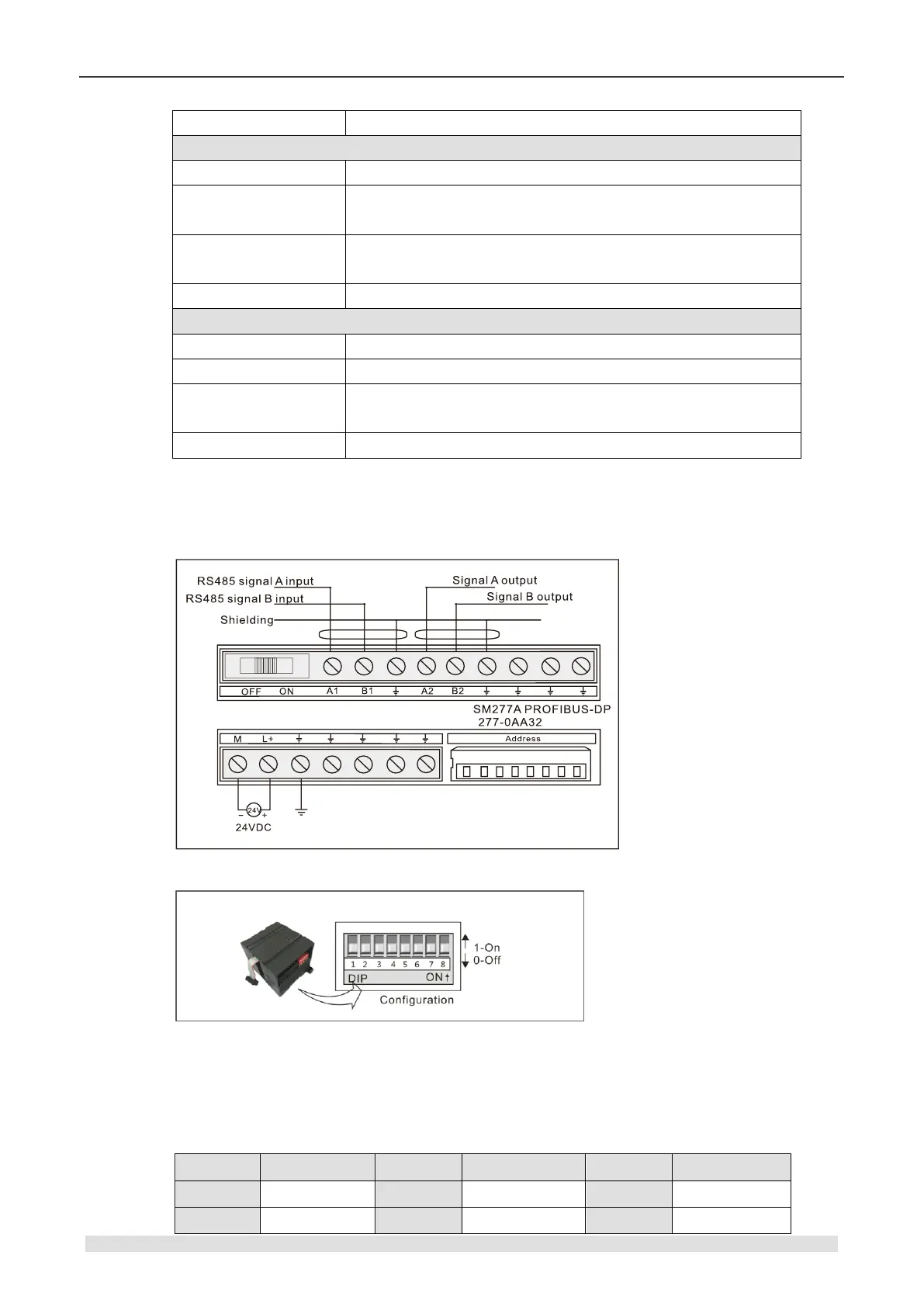
Wiring diagram
SM277A DP slave interface module (CTH2 277-0AA32)
DIP Address configuration
DIP SW1-8 (in binary), SW1 for the LSB, SW8 for the MSB (must be “OFF”), SW1-SW7 set as
“ON” - “1”, “OFF” - “0”, calculated as following:
Address=SW1×2º+ SW2×2¹ +SW3×2² +SW4×2³+ SW5×2
4
+SW6×2
5
+SW7×2
6
Table 4-7-3 Address switch configuration