CTH200 Series PLC User Manual
Unipolar 12bits, Bipolar 11bits+sign bit
Simulate input addressing
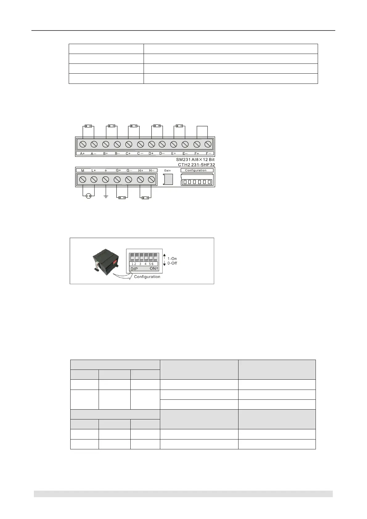
Wiring diagram
SM231 high precision AI module (CTH2 231-5HF32)
<Note> Short connect the unused terminal in the figure above, for F+ and F-.
Range selection and software configuration
【Range selection switch position】
【Range selection】
The following table shows how to set the range of SM231 8AI with DIP switch. Use 3, 4 and 5 to
select the analogy input range, use 1 and 2 to select current input mode(ON means current input
mode for channel 6, OFF means voltage mode), for switch 2, ON means current input mode for
channel 7, OFF means voltage mode.
Attention: The unused DIP switch SW4 ~ SW6 must be set to OFF.
Table 4-4-11 DIP switch configuration of SM231-5HF
4.4.2 Analog Output Module Specification
Table 4-4-12 Analog output modules specifications