CTH200 Series PLC User Manual
2) Connect the EtherNET ports of UDP_PPI master and slave for communication.
6.3.4 UDP_PPI Slave Address Mapping
The normal NETR/NETW instruction is used for UDP_PPI communication, kinds of registers can
be configured and the Address Image for slave is direct mapping.
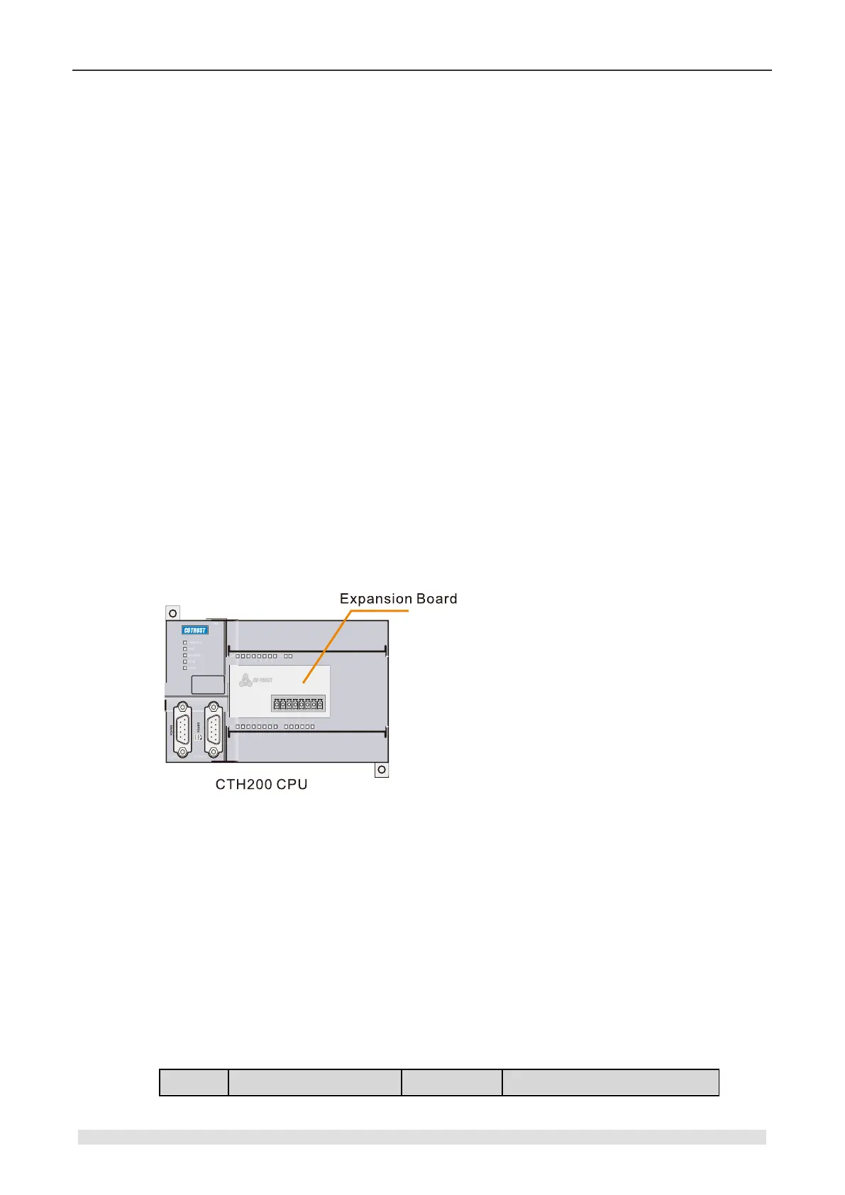
6.4 Analog I/O Expansion Board
CTH200 series CPU can be equipped with Analog I/O Expansion Board. The board embedded in
to master CPU via bus connection. It provides collected analog signals, processing results and
diagnostic information for CPU by bus interface, then the master CPU will process these data
based on specific user program and send Digital data to related expansion modules, which can
control the size of analog signals.
There are two methods to access Analog Board: calling dedicated expansion instruction library
or Access SM memory directly.
6.4.1 Installation Notes
Dismantling the up cover plate on CPU as shown in the gray box of following figure, align the
pins of expansion board to fix it, then cover the up plate, cautions for these operations.
For terminal connections between Analog Expansion Board and CPU, please refer to chapter
4.10.1 Analog Expansion Board Specifications.
6.4.2 Expansion Board Access Address
The usage for Analog expansion board is different with CAN-01 board which can be used directly
by inserting, but it must use dedicated instructions or special SM memory.
Access SM area directly
SMW116~SMW126 of CPU is used for Analog image of expansion board. First with AI, 4 words
started from SMW116; then with AQ, 2 words from SMW124.
2AI/1AQ: SMW116 for AIW0, SMW118 for AIW2, SMW124 for AQW0