CTH200 Series PLC User Manual
H.2 Components of SM277B
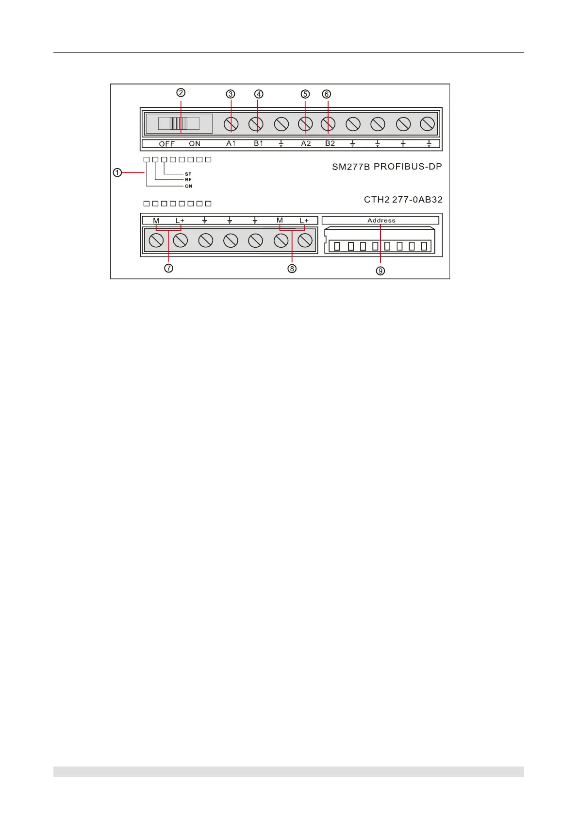
Figure H-2 SM277B structure
① Status LED
② Terminal resistance option switch: ON indicates with terminal resistance, OFF indicates
without terminal resistance
③ Isolated signal A (network input)
④ Isolated signal B (network input)
⑤ Isolated signal A (network cascade)
⑥ Isolated signal B (network cascade)
⑦ User power
⑧ Sensor power
⑨ Address switch: set with 8 bit DIP switch, indicates in binary number, effective option range is
1-125
H.3 Operating Guide
This section introduces how to use SM277B, combined with "CPU312-1AE13 and SM277B
communication" example gradually introduced SM277B hardware configuration, user
programming and debugging as well as system diagnosis.