CTH200 Series PLC User Manual
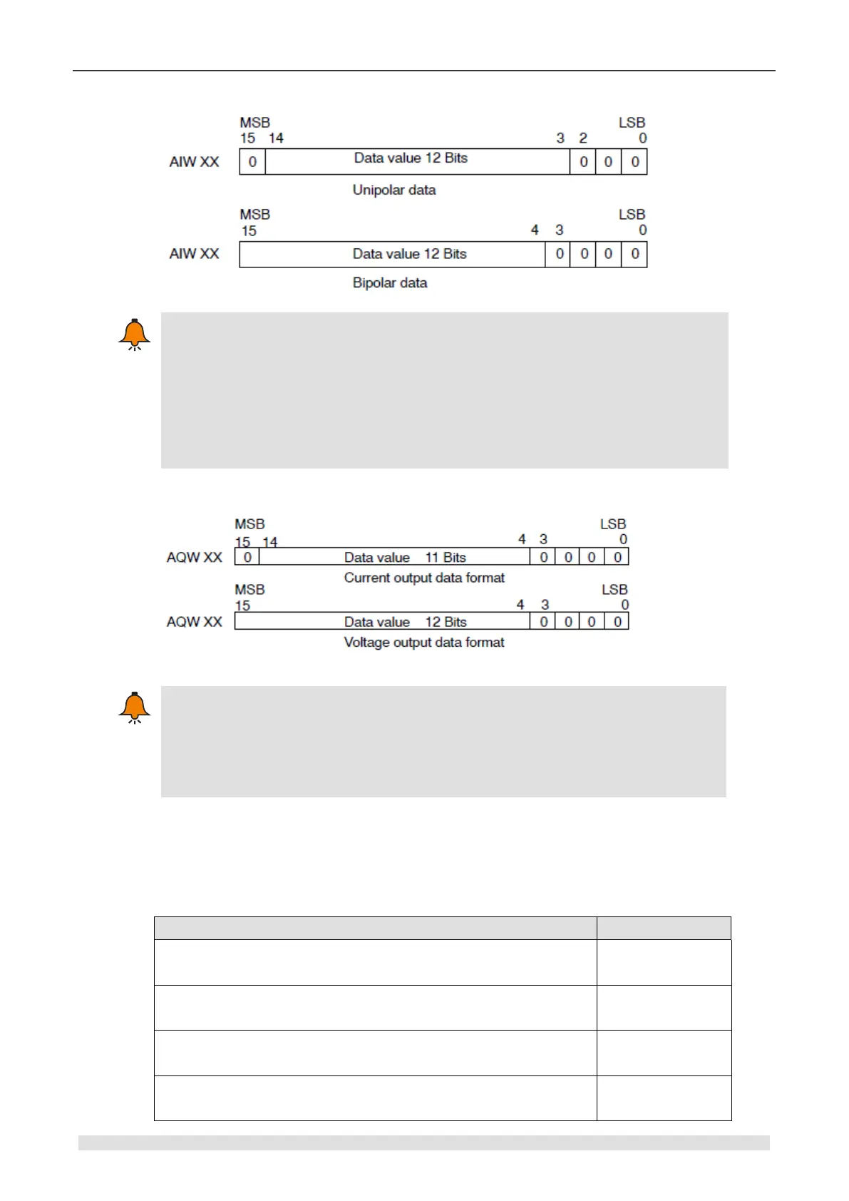
The 12 bits of the analog-to-digital converter (ADC) readings are left-justified in the data
word format. The MSB is the sign bit: zero indicates a positive data word value.
In the unipolar format, the three trailing zeros cause the data word to change by a count
of eight for each one-count change in the ADC value.
In the bipolar format, the four trailing zeros cause the data word to change by a count of
sixteen for each one count change in the ADC value.
Output Data Format
The 12 bits reading of the digital-to-analog converter (DAC) are left-justified in the
output data word format. The MSB is the sign bit: zero indicates a positive data word
value. The four trailing zeroes are truncated before being loaded into the DAC registers.
These bits have no effect on the output signal value.
4.5 Thermocouple and RTD Expansion Module Specifications
Table 4-5-1 Hybrid temperature input modules order No.
SM231 thermal resistance temperature input module, 2 RTD,
isolated 16 bits precision
SM231 thermal resistance temperature input module, 4 RTD,
isolated 16 bits precision
SM231 thermocouple temperature input module, 4 TC,
J/K/R/S/T/E/N, isolated 16 bits precision
SM231 thermocouple temperature input module, 8 TC,
J/K/R/S/T/E/N, isolated 16 bits precision