EasyManuals Logo

COTRUST CTH200 Series User Manual

COTRUST CTH200 Series
350 pages
To Next Page IconTo Next Page
To Previous Page IconTo Previous Page
Page #83 background imageLoading...
Page #83 background image
CTH200 Series PLC User Manual
73
10000Ω Pt 0.003850
1
1
0
1
1
10Ω Cu 0.004270
1
1
1
0
0
150Ω FS Resistance
1
1
1
0
1
300Ω FS Resistance
1
1
1
1
0
600Ω FS Resistance
1
1
1
1
Table 4-5-6 DIP switch settings
SW6
Calibration
SW7
Scale Unit
SW8
Wiring method
0
Upscale (+3276.7
degrees)
0
Celsius ()
0
3-wire
1
Downscale (-3276.8
degrees)
1
Fahrenheit ()
1
2-wire or 4-wire
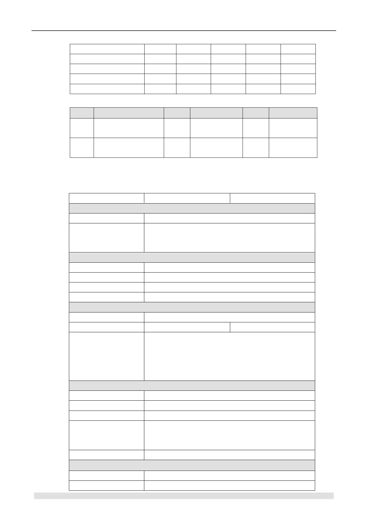
4.5.2 Thermocouple Module Specifications
Table 4-5-7 SM231 Thermocouple Module Specifications
Modules
SM231: 4AI×TC
SM231: 8AI×TC
Features
Dimension (W×D)
71.3 × 96 × 62mm
LED
24VDC indicator: ON=No fault, OFF=no 24VDC power
SF Indicator: ON=Module fault, Flash=Outrange or ,
OFF=No fault
Power
+5VDC current
87mA
L+
30mA
L+ coil voltage range
20.4~28.8VDC
Power
1.7W
Input
Input type
Float TC
Counts
4
8
Input range
TC type: S, T, R, E, N, K, J
Voltage range: +/-80mV
<Note> For temperature measuring range, please refer to
the TC measuring range in the end of this section. For error
details, please refer to the Table 4-5-8 and 4-5-9.
Isolation
Field to Logic
500VAC
Field to 24VDC
500VAC
24V to Logic
500VAC
Common mode input
range (input channel to
input channel)
120VAC
Common mode rejection
>120dB@120VAC
Sampling features
Temperature resolution
0.1/0.1
Voltage resolution
15 bits + sign bit

Table of Contents

Questions and Answers:

Question and Answer IconNeed help?

Do you have a question about the COTRUST CTH200 Series and is the answer not in the manual?

COTRUST CTH200 Series Specifications

General IconGeneral
BrandCOTRUST
ModelCTH200 Series
CategoryController
LanguageEnglish