EasyManuals Logo

COTRUST CTH200 Series User Manual

COTRUST CTH200 Series
350 pages
To Next Page IconTo Next Page
To Previous Page IconTo Previous Page
Page #121 background imageLoading...
Page #121 background image
CTH200 Series PLC User Manual
111
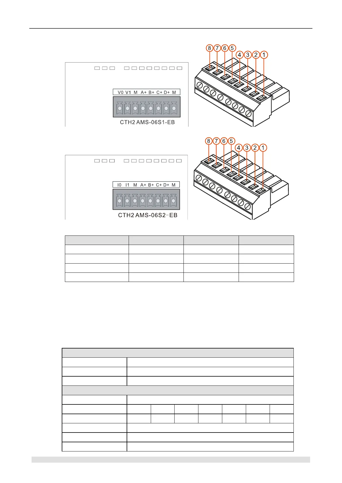
Table 4-10-4 AMS-06 Terminal definition
Terminal
Signal definition
Terminal
Signal definition
1
Output V0/I0
5
Analog Input B+
2
Output V1/I1
6
Analog Input C+
3
Ground GND-M
7
Analog Input D+
4
Analog Input A+
8
Ground GND-M
<Note> A+/B+/C+/D+ are voltage inputs for positive or negative voltage, V1 must be connected
with Terminal 3, D+ connected with Terminal 8. M is the common Ground, any output connecting
directly with M is not allowed, or it will cause output short.
4.10.2 CAN Expansion Board Specifications
Table 4-10-5 Specifications of CAN-01 expansion board
Basic features
Dimension (W×D)
137 x 96 x 62mm
Suitable product
CPU H224X/H226XL/H228XL
Power dissipation
9W
CANopen communication
Communication interface
1 (8 Pin)
Transmission rate (kbps)
1000
800
500
250
125
50
20
Max length (m)
25
50
100
250
500
1000
2500
Max station address
127
Station address range
1-127
Max number of slaves
32

Table of Contents

Questions and Answers:

Question and Answer IconNeed help?

Do you have a question about the COTRUST CTH200 Series and is the answer not in the manual?

COTRUST CTH200 Series Specifications

General IconGeneral
BrandCOTRUST
ModelCTH200 Series
CategoryController
LanguageEnglish