CTH200 Series PLC User Manual
interval. This example uses the ladder diagram editor to enter the program, and describes the
program compilation, download and operation process.
Pictures below shows the ladder diagram and statement list to explain logic relationship in the
program.
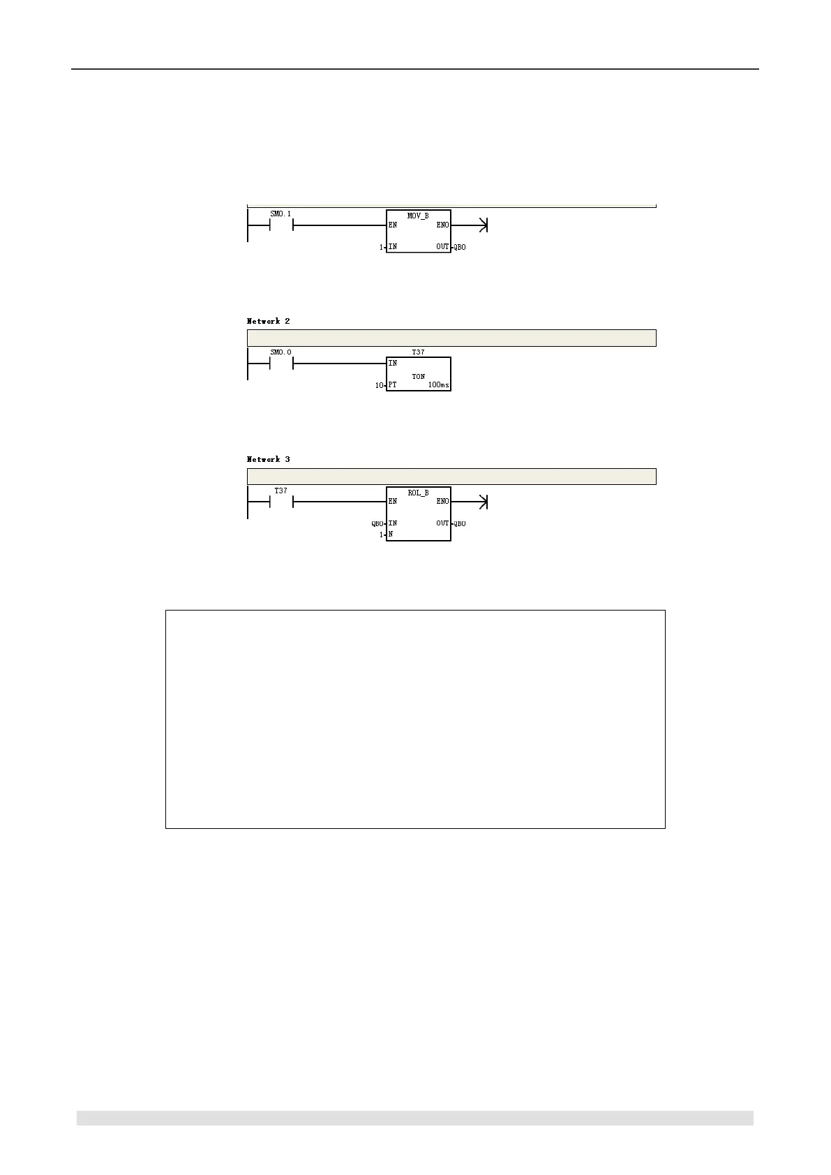
Figure 2-7 Example of CTH200 program
Segment comment:
LD SM0.1 // Enable by first scan of SM0.1
MOVB 1, QB0 // Transfer 1 into QB0
Network 2:
LD SM0.0 // Enable signal
AN T37 // Circulate timer signal
TON T37, 10 // Set timer T37, Time 100ms x 10 = 1s
Network 3:
LD T37 // Set enable pulse via T37
RLB QB0, 1 // QB0 shift 1 bit left, with the PLC LEDs light on at 1s interval.
2.3.1 Editing
Click the Program Block to open the program editor, as shown in figure 2-8. User can drag&drop
the ladder instructions into program editor, or use the shortcut for available instructions directly.