Appendix
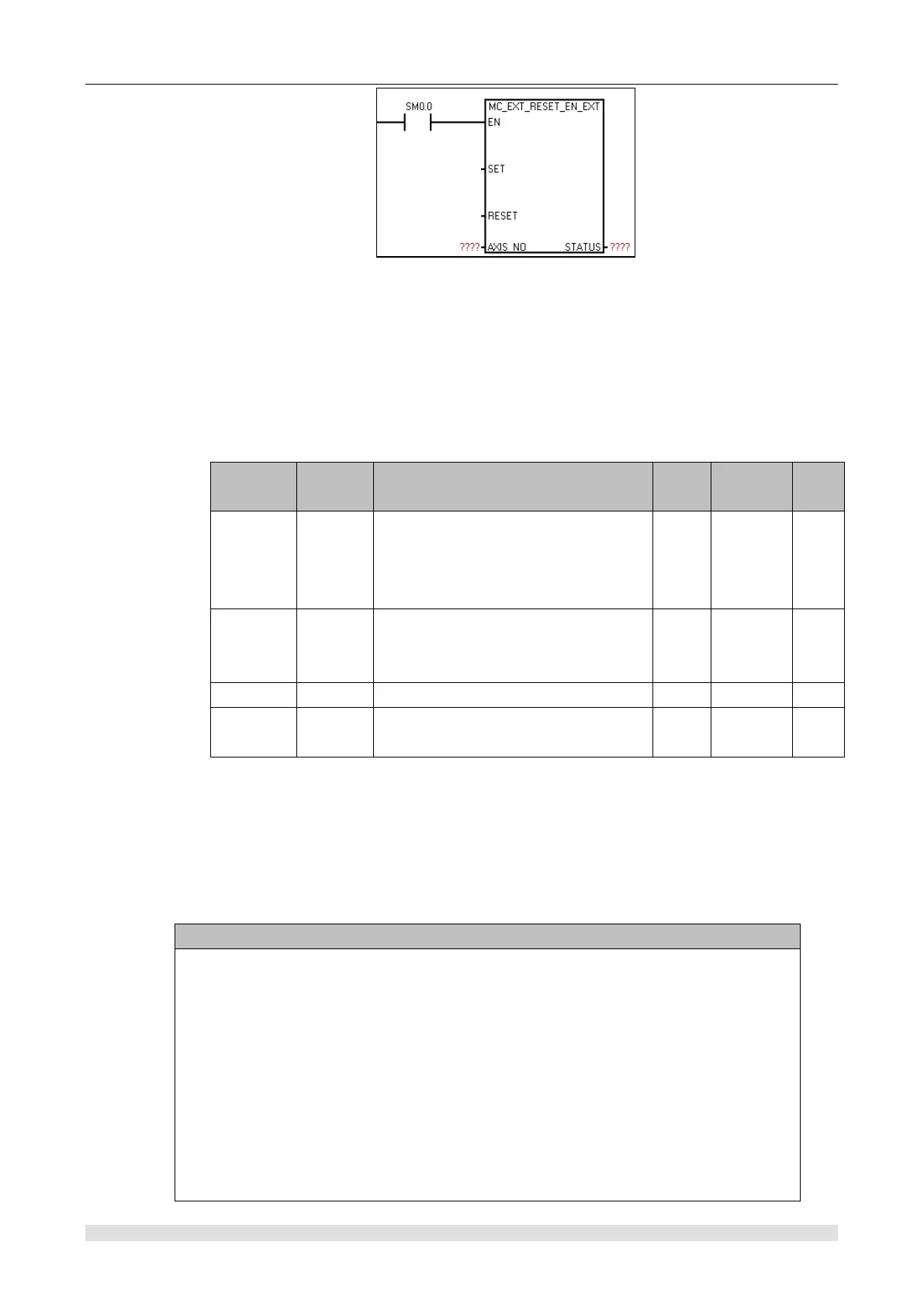
②Function: Set if enable external IO reset absolute coordinate
Note: Correspondence of axis number and external reset signal
Axis 0 ——I0.2 (HSC0, SM37.0)
Axis 1 ——I1.0 (HSC1, SM47.0)
Axis 2 ——I1.4 (HSC2, SM57.0)
Axis 3 ——I0.5 (HSC4, SM147.0)
③
Parameter
Set absolute coordinate 0 at SET
rising edge, set SET 0, then set 1 for
each call
RESET rising edge, forbid to enable
external reset, RESET then set 0 for
each call
④ Explanation
Use 0 axis to call this instruction. After the SET rising edge enables the external reset function
and I0.2 detect the "effective reset signal", the system resets the axis 0 absolute coordinate, and
also the STATUS setting reset complete. After the RESET rising edge prohibits the external reset
function, even if I0.2 detect the "effective reset signal", the system will not reset the 0 axis
absolute coordinate, and the STATUS reset instruct is non-reset state.
The so-called "effective reset signal", the reset signal of each axis corresponding to an
external IO, and the corresponding register set its effective level. For example, 0 axis
corresponds to I0.2, and HSCO control register SM37.0 set the effective reset level of 0
axis. When set to 0, the effective reset signal of 0 axis is in I0.2 high level. When set to 1,
the effective reset signal of axis 0 is in I0.2 low level; This setting is only effective if and
only if the corresponding high-speed counter (0 axis corresponds to HSC0) is enabled,
otherwise (no high-speed counter is enabled) the system default high level is the effective
reset signal. If 0 axis, I0.2 high level is the effective reset signal. In the same way for other
axes, the corresponding relation of the relevant control of each axis is shown in ② of this
section.