Appendix
configuration in STEP7, no need to configure and program the communication in CTH200
system, just sort out the data to be communicated and store it in the V storage area
corresponding to the hardware I/O address of S7-300 configuration SM277A slave station.
Write program to call FC1 (DP_SEND) and FC2 (DP_RECV) in OB1, DP master can read and
write from the slave station data to achieve S7-300 and CTH200 CPU communication. Execute
the DP_SEND instruction to output the memory data of CTH200 CPU to the SM277A extension
module. By performing DP_RECV, input the SM277A extension module data to the memory of
CTH200 CPU.
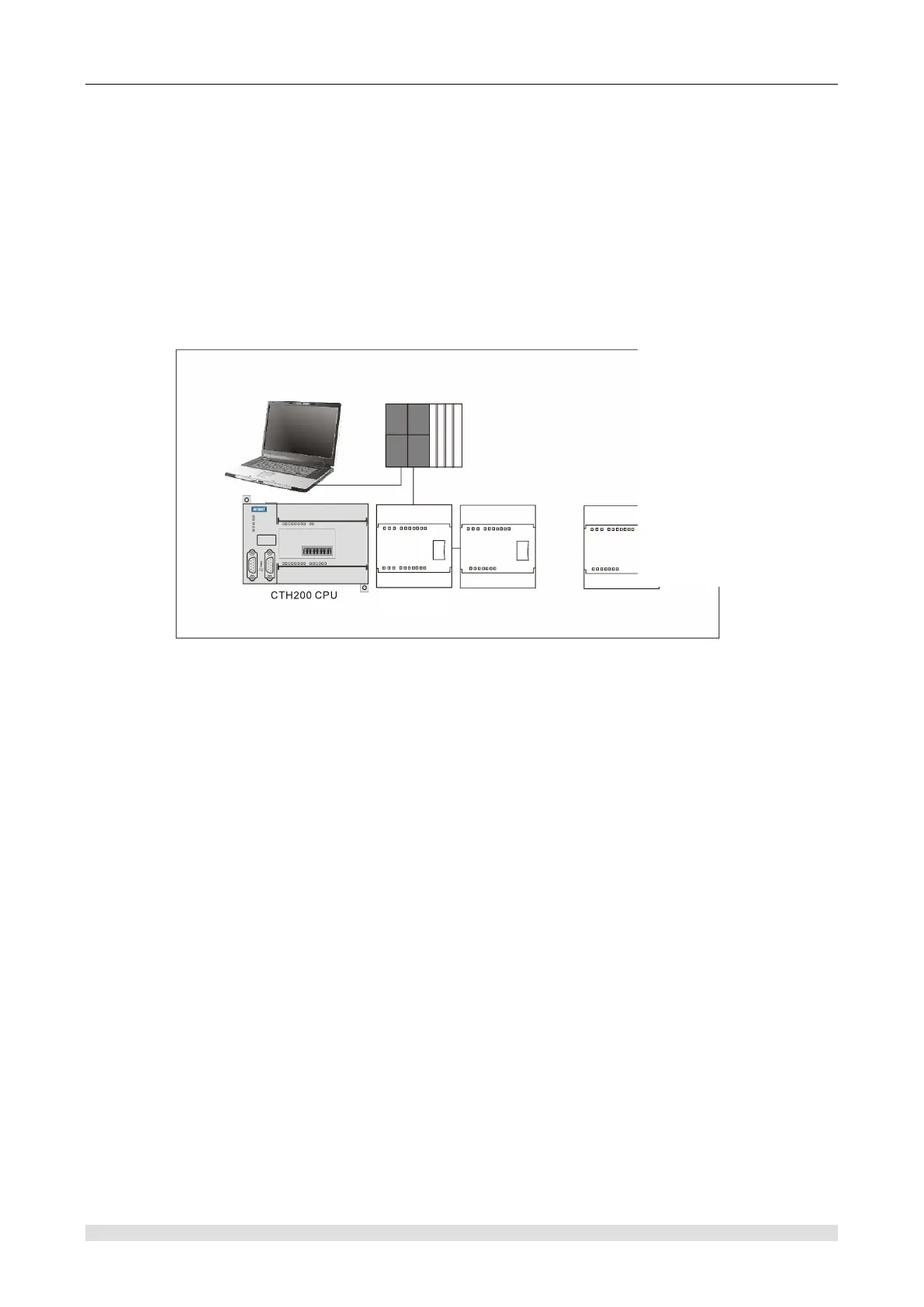
Figure G-1 shows a PROFIBUS network with CTH200 CPU and SM277A DP slave station
module.
S7-315-2DP
.......
Expansion modules
EM277A
PG/PC
MPI
PROFIBUS connection
Figure G-1 PROFIBUS network example
Use S7-300 with CPU 315-2 as the DP master station, and configure with STEP 7
programming software.
CTH 200 CPU is DP slave station of CPU 315-2 DP master station.
CPU 315-2 DP master station use DP_SEND and DP_RECV of user program to read and
write data from CTH200.
Note: To use SM277A as a DP slave, you must set the DP port address that matches in the
master group. The slave station address is set by DIP switch of SM277A module.
MPI communication between S7-300 and SM277A of CTH200
When CTH200 CPU and S7-300 conduct MPI communication, no need to write any program
related to communication in CTH200 PLC, just set the data for exchange into continuous V
storage area, and in S7-300 need to call system function X_GET (SFC67) and X_PUT (SFC68)
in OB1 (or timer interrupt tissue block OB35) to realize the communications between S7-300 and
CTH200 CPU, When call SFC67 and SFC68, the VAR_ADDR parameter is filled in the data
address area of CTH200, where P# db1.* * * BYTE n corresponds to the data area from VB * * to
VB (* * +n) in the CTH200 CPU V storage area.
Figure G-2 shows an MPI network with CTH200 CPU and EM277A DP slave station module.