CTH200 Series PLC User Manual
value, select the sampling times above 64.
Calibration steps:
1) Cut off external power of modules, configure DIP switch to select needed range.
2) Connect CPU with module power, wait for 15min above.
3) Use a transmitter, a voltage input source or a current input source to add the zero signal to
module input.
4) Read measurement of the input in CPU.
5) Adjust OFFSET potentiometer till the reading is zero, finish zero set calibration.
6) Input a full scale signal to read the measurement in CPU.
7) Adjust GAIN potentiometer till the reading is 32000.
8) Repeat 3~7 when necessary.
【Select range】
The following table shows how to set the range of SM231 4AI with DIP switch. Use 1, 2 and 3 to
select the analogy input range which can be set to the same.
Attention: the unused DIP switch SW4 ~ SW6 must be set to OFF.
Table 4-4-3 DIP switch configuration of SM231-0HC
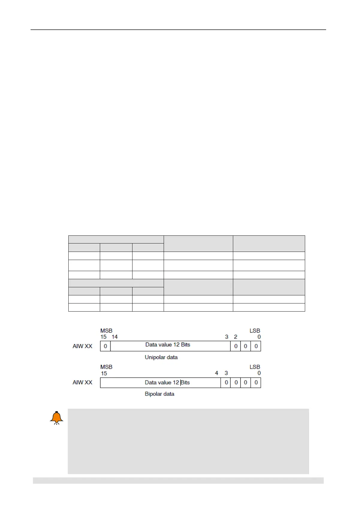
Input Data Format
The 12 bits of the analog-to-digital converter (ADC) readings are left-justified in the data
word format. The MSB is the sign bit: zero indicates a positive data word value.
In the unipolar format, the three trailing zeroes cause the data word to change by a count
of eight for each one-count change in the ADC value.
In the bipolar format, the four trailing zeroes cause the data word to change by a count of
sixteen for each one count change in the ADC value.