CTH200 Series PLC User Manual
Range selection and software configuration
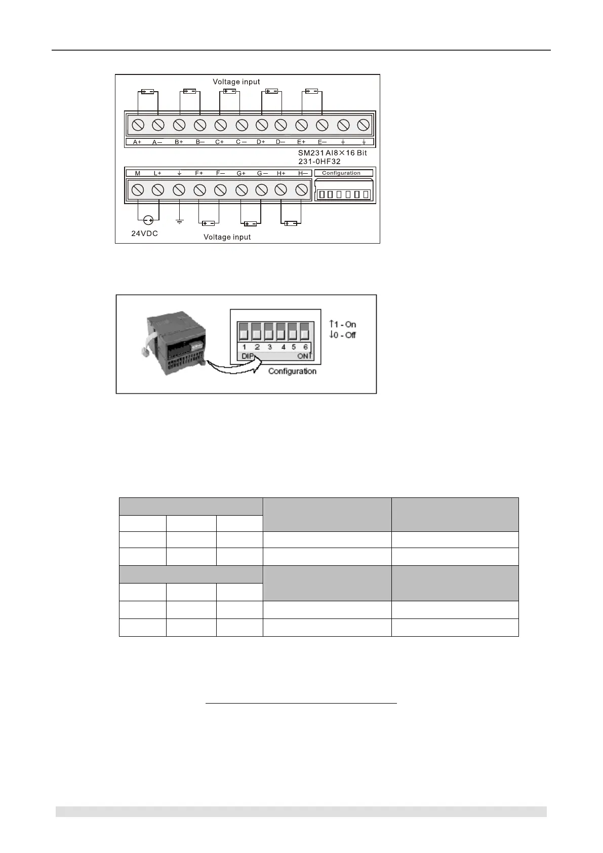
【Range selection switch position】
【Range selection】
The following table shows how to set the range of SM231 8AI with DIP switch. Use 1, 2 and 3 to
select the analogy input range which can be set to the same.
Attention: The unused DIP switch SW4 ~ SW6 must be set to OFF.
Table 4-4-5 DIP switch configuration of SM231-0HF
【Software Configuration】
For SM231 8AI×16 bits, reading in VW instead of AIW. The relative location of the module is
different, so is the corresponding address. Calculation formula:
x(VWx) = Slot no. × 64 + Input channel × 2
The slot number of the address quick reference table corresponds to the installation location of
the module. The first expansion module close to the CPU has the slot number of 0, the second
expansion module has the slot number of 1, and so on. There are 8 input channels, from A to G,
and the corresponding number is 0 to 7.