EasyManuals Logo

COTRUST CTH200 Series User Manual

COTRUST CTH200 Series
350 pages
To Next Page IconTo Next Page
To Previous Page IconTo Previous Page
Page #95 background imageLoading...
Page #95 background image
CTH200 Series PLC User Manual
85
Usage specifications
Insulation thermocouple should be used to achieve good immunity from interference
Use Shielded wire, grounded, as signal line.
GND terminal must be connect to the ground.
Short unused channels to eliminate the Break line fault alarm
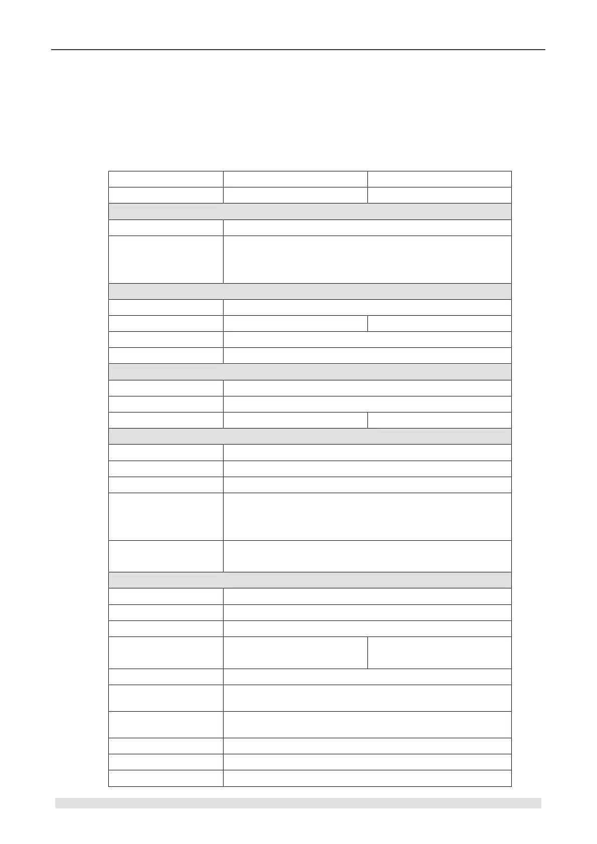
Table 4-6-2 SM231-7TD/7TF thermocouple PID module specifications
Modules
SM231 4AI×TC PID
SM231 8AI×TC PID
Order No.
CTH2 231-7TD32
CTH2 231-7TF32
Features
Dimension (W×D)
71.3 × 96 × 62mm
LED indicator
24VDC indicator: ON=No fault, OFF=no 24VDC power
SF Indicator: ON=Module fault, Flash=Out range or
disconnect, OFF=No fault
Power supply
+5VDC current
87mA
L+
34mA
39mA
L+ coil voltage range
20.4~28.8VDC
Power
1.8W
Input
Type
Float TC
Range
K-type TC
Counts
4
8
Isolation
Field to Logic
500VAC
Field to 24VDC
500VAC
24VDC to Logic
500VAC
Common mode input
range (input channel to
input channel)
120VAC
Common mode
rejection
>120dB@120VAC
Sampling features
Temperature resolution
0.1/0.1
Voltage resolution
15bits + sign bit
Transfer principle
Σ-Δ
Module update time: All
channels
405ms
825ms
Wire length to sensor
Max 100m
Conductor loop
resistance
Max 100Ω
Suppression of
interference
85dB@ 50Hz/60Hz/400Hz
Data word format
Voltage: -27648~+27648
Input impedance
>1MΩ
Max. Input voltage
30VDC

Table of Contents

Questions and Answers:

Question and Answer IconNeed help?

Do you have a question about the COTRUST CTH200 Series and is the answer not in the manual?

COTRUST CTH200 Series Specifications

General IconGeneral
BrandCOTRUST
ModelCTH200 Series
CategoryController
LanguageEnglish