Linea Lite GigE Series Camera Technical Specifications • 145
Connectors
• RJ45 Ethernet connector for control and video data to the host Gigabit NIC. For industrial
environments, Linea GigE supports the use of screw lock Ethernet cables (see
Ruggedized RJ45
Ethernet Cables).
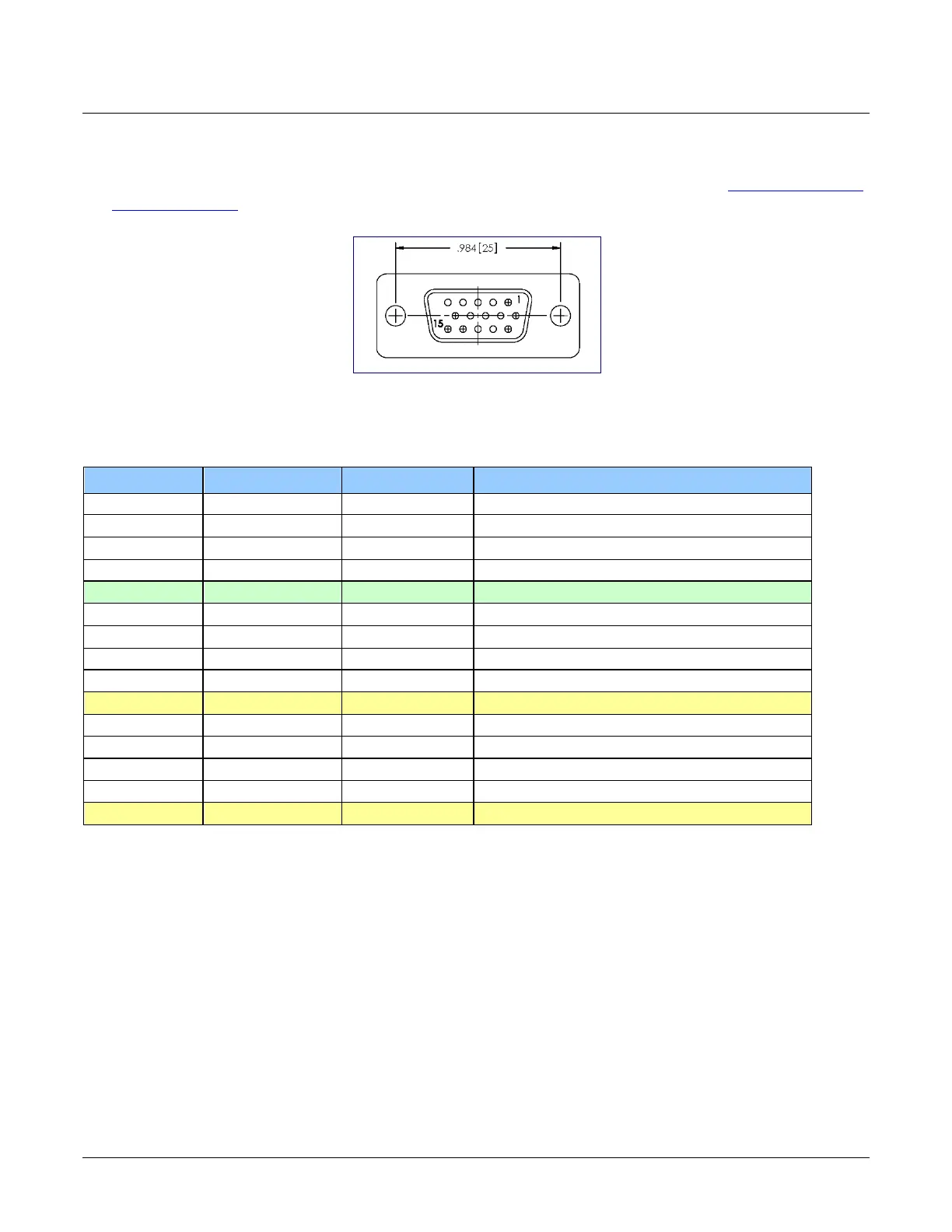
• A single HD15 female connector for all I/O and DC power source.
Figure 102: HD15 Female Connector
HD15 Connector Details
Pin Number Linea Lite GigE Direction Definition
1 Line 1+ In RS-422
[1]
Input Port 1+
2 Line 1- In RS-422
Input Port 1-
3 Line 2+ In RS-422
[1]
Input Port 2+
4 Line 2- In RS-422
[1]
Input Port 2-
5 Signals Ground Signals Ground
6 Line 3+ In/Out Configurable
[2]
IO Port 3+
7 Line 3 - In/Out Configurable
[2]
IO Port 3-
8 Input Trigger Level Out
9 Input Trigger Level Out
10 PWR-GND Camera Power Ground
11 Line 4+ Out Configurable
[3]
Output Port 4+
12 Line 4- Out Configurable
[3]
Output Port 4-
13 Line 5+ Out Configurable
[3]
Output Port 5+
14 Line 5- Out Configurable
Output Port 5-
15 PWR-VCC Camera Power – DC +12 to +24 Vdc
[1]: Programmable RS422 termination
[2]: Line 3 is programmable as:
• Single ended input with programmable threshold
o 0-24 V in (0-60 V tolerant)
o 0-11 V threshold voltage
• RS422 In (external termination required)
• RS422 Out
• 3.3 V single ended output
[3]: Line 4 and 5 are programmable as:
• RS422
• Single ended 3.3 V open collector output

 Loading...


