Linea Lite GigE Series Camera Operational Reference • 87
Timer Start Source timerStartSource Select the trigger source to start the timer. The Event
Control section provides details and timing diagrams for
DFNC
TimerReset Cmd Off Starts with the reception of the TimerReset Icommand.
Acquisition Start AcquisitionStart Start Timer on Acquisition Start event.
Start Timer on Acquisition End event.
Exposure Start ExposureStart Start Timer on Exposure Start event.
Exposure End ExposureEnd Start Timer on Exposure End event.
Frame Start FrameStart Start Timer on Frame Start event.
Frame Trigger ValidFrameTrigger Start Timer on Valid Frame Trigger event.
Start Timer on Invalid Trigger event.
Line 1 Line1 Start Timer on a transition of I/O Line 1 event.
See Input Signals Electrical Specifications.
Line 2 Line2 Start Timer on a transition of I/O Line 2 event.
Line 3 Line3 Start Timer on a transition of I/O Line 3 event.
Timer 1 End Timer1End Start Timer on Timer 1 End event.
Counter 1 End Counter1End Start Timer on Counter 1 End event.
Timer Line Activation timerStartLineActivation Select the trigger activation mode which starts the timer.
DFNC
Rising Edge RisingEdge Starts counter on rising edge of the selected signal.
Falling Edge FallingEdge Starts counter on falling edge of the selected signal.
Any Edge AnyEdge Starts counter on the falling or rising edge of the
selected signal.
timerDuration Sets the duration (in microseconds) of the timer pulse.
Timer Value timerValue Reads the current value (in microseconds) of the selected
DFNC
Timer Reset timerReset Resets the timer to 0.
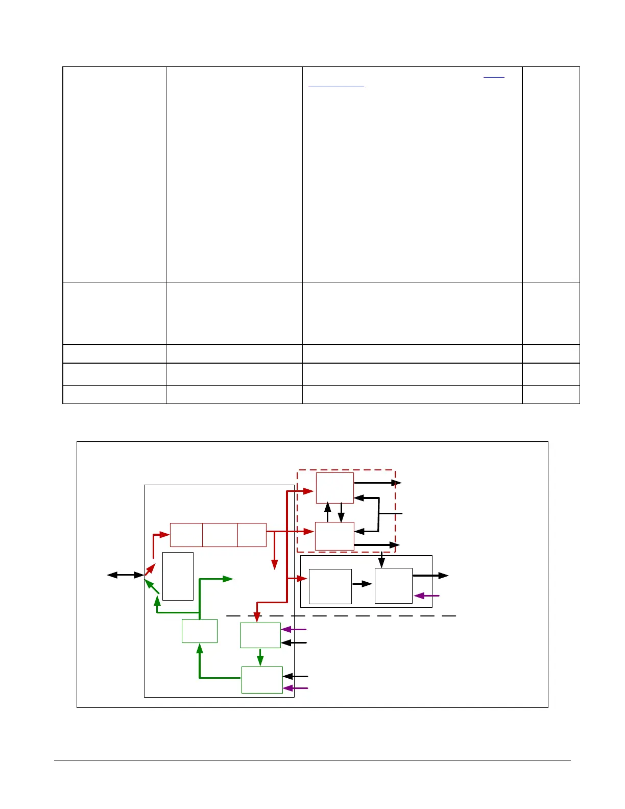
Counter and Timer Group Block Diagram
Line Selector =
Line 1 to 5
Physical
Line
Event Driven
Input
Inverter
Output
inverter
Software Driven
Pulse
Generator
LineStatus
Trigger
Line
Activation
Trigger Signal
Timer
TimerEnd Event
CounterEnd Event
Software Trigger
Cmd
Line
Mode
Input
or
Output
Input
Output
Timer and Counter Module
Counter
Line
Debouncer
Event Driven
Trigger
Source
Trigger Module
Output
Line
Source
Signal Driven
Software Driven
Line
Detection
Level
Figure 70: Counter and Timer Group Block Diagram

 Loading...


