148 • Technical Specifications Linea Lite GigE Series Camera
Input Signals Electrical Specifications
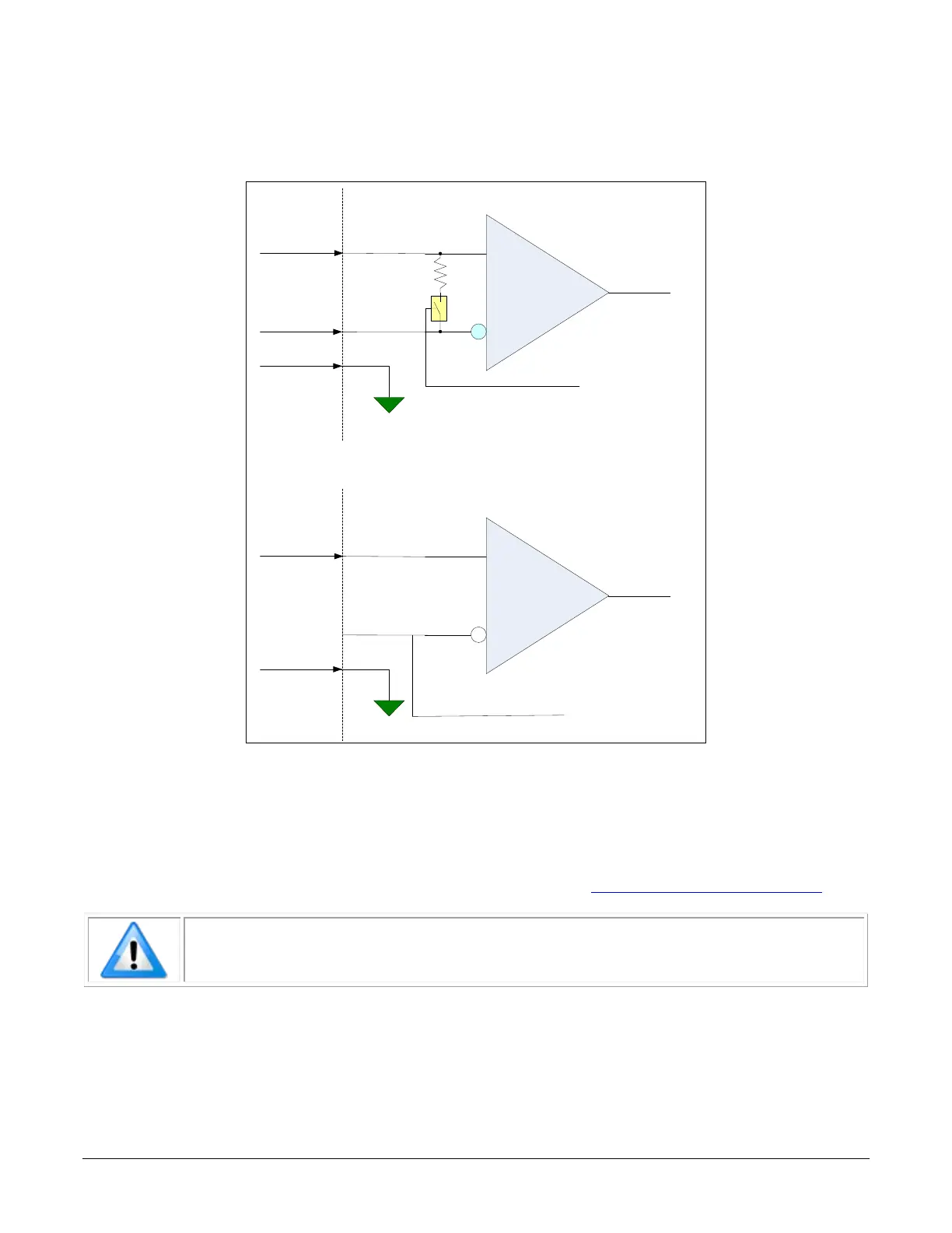
External Inputs Block Diagrams
Balanced RS422 Receive Mode
Termination Enable
Receive Input
INPUT (+)
PIN 5
INPUT (-)
Signal Ground
External
Signal
Line 3 Single
-
Ended Logic Receive Mode
3.3V, 5V, 12V, 24V
Receive Input
INPUT (+)
PIN 5
INPUT (-)
not connected
Signal Ground
External
Signal
Programmable Input Threshold
Figure 104: External Inputs Block Diagram
External Input Overview
• The input signals can be used as trigger acquisition event, counter or timestamp event, or
integration control.
• The input signal can be improved by user programmable Input Line Debouncing Period
from
0 to 255 µs, in 1 µs steps.
• Caution:
It is important to correctly configure external inputs before connecting
external signals. Connecting higher voltage signals to inputs configured as
RS422 may damage the inputs.

 Loading...


