Functions
◦ Remote commands start sequences (from Modbus, digital inputs, PICUS, CustomLogic
and/or CODESYS)
◦ Display unit push-buttons for breaker open and close are ignored
• LOCAL mode
◦ Display unit push-buttons start one-touch sequences
◦ Remote commands for breaker open and close are ignored
Display unit for GENSET controller
This folio is only for the GENSET controller application.
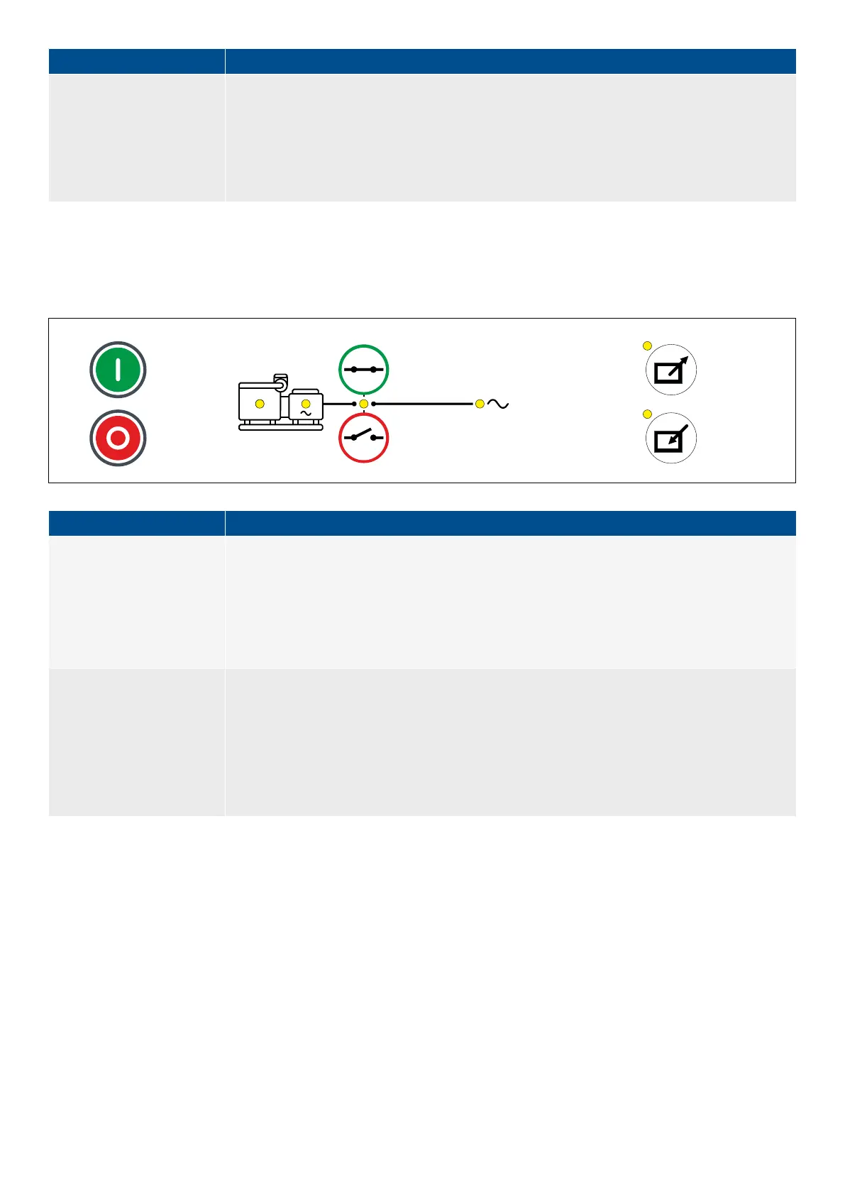
Figure 3.4
Example of display unit for GENSET with full functionality (LEDs shown in yellow)
Functions
Display unit with full
functionality
• LEDs for generator and busbar V&Hz
• LEDs for engine and breaker status
• Display unit push-buttons
◦ Change control mode (LOCAL/REMOTE)
◦ One-touch sequences for breaker open and close
◦ One-touch sequences for genset start and stop
Control modes
• REMOTE mode
◦ Remote commands start sequences (from Modbus, digital inputs, PICUS, CustomLogic
and/or CODESYS)
◦ Display unit push-buttons for breaker open and close, and genset start and stop are ignored
• LOCAL mode
◦ Display unit push-buttons start one-touch sequences
◦ Remote commands for breaker open and close, and genset start and stop are ignored
3.1.3 Display unit LEDs and push-buttons
The top part of the front of the display unit is the same for all controller types. It includes LEDs that show the controller status and a
push-button to silence the alarm horn. The other push-buttons allow the operator to see controller information on the display unit
screen. The actual information available to the operator depends on the permission access for the operator's log on profile.* Using
the push-buttons and the screen, the operator can see Live Data, or see, acknowledge and unlatch alarms. If the operator logs in
with the right permission level, he can also change the controller configuration.
* Some features or functions of the display unit may only be accessible if the user profile logged on has the necessary permission
access.
OPERATOR'S MANUAL 4189341099G UK Page 17 of 130