DA20-C1 Flight Manual
Description
Doc # DA202-C1 April 06, 2010 Page 7 - 21
7.11. ELECTRICAL SYSTEM
Revision 25
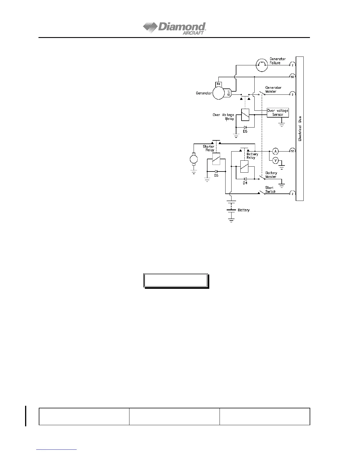
Simplified Schematic (see Figure 7.7)
7.11.1. Power Supply
A 12 V battery is connected to the master
bus via the battery circuit breaker (50
Amps). The 40 amp. generator is attached
to the engine near the propeller hub. The
generator feeds the main bus via the
generator circuit breaker (50 Amps). Both
circuit breakers can be triggered manually.
The generator warning light is activated by
an internal voltage regulator monitoring
circuit and illuminates when a generator
fault occurs.
7.11.2. Ignition System
The engine is provided with two
independent ignition systems. The two
magnetos are independent from the power
supply system, and are in operation as soon
as the propeller is turning and the ignition
switch is not off. This ensures safe engine
operation even in case of an electrical
power failure.
Figure 7.7. Simplified Schematic
WARNING
IF THE IGNITION KEY IS TURNED TO L, R OR BOTH, THE
RESPECTIVE MAGNETO IS "HOT". IF THE PROPELLER IS
MOVED DURING THIS TIME THE ENGINE MAY START AND
CAUSE SERIOUS OR FATAL INJURY TO PERSONNEL. THE
POSSIBILITY OF A ‘HOT’ MAGNETO MAY EXIST DUE TO A
FAULTY SWITCH OR AIRCRAFT WIRING. USE EXTREME
CARE AND RESPECT WHEN IN THE VICINITY OF A
PROPELLER!